THE IDEA
This mod is to basically develop a PS3 slim model CECH-25xx motherboard adapter plate and wiring adaptors that are able to be transplanted between different PC cases with no modification to the PC case and only a few minor modifications to the PS3 motherboard.REASONS
- Have a bigger style heatsink so that the PS3 CPU and GPU runs cooler.
- Allow the motherboard exposure to more air rather than being in close proximity to a heated metal chassis.
- Motherboard steel chassis's rust and the rust particles fall on to the motherboard and cause shorts.
- Easily change the motherboard clock battery.
90%
TASKS
Current:
Create the Processor heatsinks
Complete:
Create the PS3 motherboard adapter plate
Create the custom clamping hardware (flat bottom heatsink)
Create the custom clamping hardware (flat bottom heatsink)
Create the PS3 On/off to PC case wiring adapter.
Create the PS3 LED to PC case wiring adapter.
Not Complete:
Extras: (Not important so I might do later on)
PS3 MOTHERBOARD
The chosen PS3 motherboard will be from CECH-25xx model PS3 slims due to being able to be jailbroken therefore they can play games off of the hard drive.
Also the disk drive circuit board is incorporated into the motherboard therefore it does not require the actual disc drive to be attached to launch games and apps unlike all earlier model CECHAxx to CECH-21xx PS3s that do.
The PS3 CECH-25xx model motherboards measure about:
Width=257mm (Including USB port to rear ports)
Height=260mm
ADAPTER PLATE
Details:
The PS3 motherboard is to be mounted onto a custom made ATX aluminium adapter plate measuring 305mm x 255mm x 1.5mm thick. The purpose of the adapter plate is to combine the standoff holes from the PS3 motherboard and PC case onto the one plate.
Orientation:
The motherboard will be oriented so that the USB ports will be accessible through the PC case rear IO port area and the rear ports on the PS3 motherboard will be facing toward the front of the PC case.

Procedure:
I used the PS3 and PC motherboards as templates to drill the standoff adapter plate holes depending on the motherboard version. The basic process is as follows:
1. Clean the aluminium plate edges of any burs
2. Clamp the motherboard in place
3. Use a bench drill-press to lightly mark the standoff holes using the following drill sizes:
1. Clean the aluminium plate edges of any burs
2. Clamp the motherboard in place
3. Use a bench drill-press to lightly mark the standoff holes using the following drill sizes:
3mm - PS3
3.5mm - PS3
11/64 4.35mm - PS3
4mm - PC
4. Drill the PS3 clamping hardware holes - See the text following this section for more info.
5. Remove the clamps and motherboard
6. Drill the marked holes all of the way through using the following drill sizes:
3mm - PS3
4mm - PS3/PC
7. Remove the burs from the drill holes
Drilling the Clamping Hardware Holes:
To make sure the clamping bolts as close to centered as possibly on the aluminium adapter plate you can either:
Option 1 - Recommended
Create a custom spacer 6.5mm wide with a 3mm hole drilled through the centre. Place the spacer in each of the four motherboard clamping hardware through-holes before drilling a 3mm hole through the adapter plate.
NOTE: The 3mm drill hole in the middle of the 6.5mm spacer must be perfectly centered within the spacer.
Option 2 - Not Recommended
With the PS3 motherboard sitting on standoffs the shorter the better, using a bench drill and a 6.5mm drill bit it is possible to drill straight down through each of the four motherboard clamping hardware through-holes.
NOTE: ONLY USE IF you cannot make the spacers listed previously as this method is less accurate.
NOTE: If the drill grabs the motherboard clamping hardware hole it will widen out the hole making the centre mark less accurate.
NOTE: If the drill is bent it may result in out of place center markings. The higher the standoffs the worse the issue can be.
Example PS4.


PS3 motherboard mounted.

HINT: For the best results in standard ATX cases position the PS3 motherboard so that the PS3 motherboard top edge sits 10mm lower than the PC motherboard top edge. This is so that one of the PS3 motherboard standoff mounting hole bolts don't collide with a PC standoff screw.
HINT: For the most accurate standoff hole locations in the adapter plate get faulty PS3 and PC motherboards. Then grind the motherboard bottom till all of the SMD components and protruding through hole component legs are gone and the motherboard bottom surface is flat.
WARNING: YOU SHOULD WEAR A FACE MASK TO STOP INHALING PARTICLES THAT MIGHT CAUSE INJURY OR ILLNESS.
Grinded PS3 motherboard.

Grinded PC motherboard.

COOLING
CPU RAM:
Processors:
I have used the GPU heatsink from a CECH-3002 PS3 as a template to cut the perfect heatsink base-plate shape from 3mm thick copper plate. I cut the fins off of the CECH-3002 GPU heatsink leaving only the base-plate. Then I sanded and filed both sides so that they are reasonably flat. I then clamped the CECH-3002 GPU heatsink base-plate to the 3mm copper plate then drilled the two mounting holes and marked the outer base-plate shape. Then bolted the CECH-3002 GPU heatsink base-plate to the other side and once again mark the outer shape. Next cut, filed and sanded the 3mm copper plate till it matched the CECH-3002 GPU heatsink base-plate shape. I then shortened the overall length of the base-plate so that they don't collide with the four nearby inductors/coils that are grey in color that can be seen in a picture below.
Finally I soldered a heatpipe heatsink to it. I have build two of these heatsinks.
Modified CECH-3002 GPU heatsink base-plate. Ready to template.

Final copper base-plates.

Final heatpipe heatsink soldered to base-plate.


NOTE: With the base-plate shape that you see one of the electrolytic capacitors will collide with the CELL/CPU heatsink base-plate. As a simple workaround I will snap-off or de-solder this, move it over slightly and extend the capacitor legs. I prefer this method over modifying the base plates.
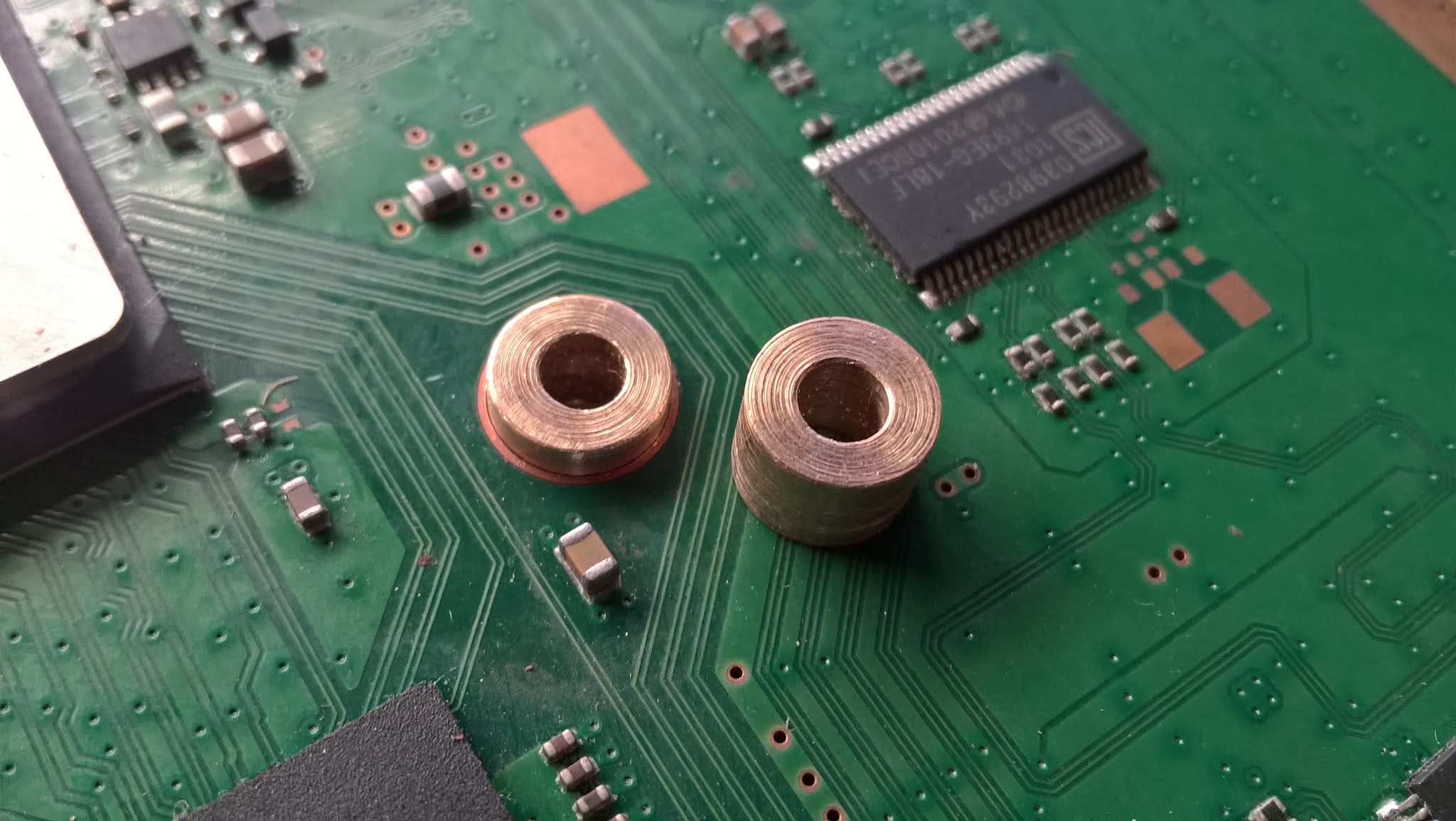
Clamping
Connect the heatsink to the adapter plate using official clamps and created custom spacers.
Order:
1. 3mm bolt
2. Adapter plate
3. Lower brass spacer. With center 3mm threaded hole. Use for all heatsink types.
CPU: 7.1mm (H) x 8mm (W)
GPU: 7.1mm (H) x 8mm (W)
4. Upper brass spacer. With centre 3mm hole through the centre. These measurements of spacers are only for flat bottom heatsinks. Other heatsinks types where the processor contact area is at a different level to the clamping hardware will require different length spacers.
CPU: 7.55mm (H) x 5.7mm (W) (Official) or 5mm (W) (Custom)
GPU: 9mm (H) x 5.7mm (W) (Official) or 5mm (W) (Custom)
5. PS3 I-clamp.
6. PS3 I-clamp motherboard backing plate.
7. PS3 motherboard
8. Heat sink base-plate
9. 3mm nut
Without clamping hardware.

With clamping hardware.

WARNING: Care must be taken when inserting or removing the motherboard as it is more likely to flex when doing so due to the spring state of the I-clamp. Proper procedure after placing the motherboard is to mount the heatsink then tighten the four heatsink nuts. Next screw in the rest of the motherboard to adapter plate standoff screws. Removing the motherboard should be done in the reverse order.
The metal chassis clamp backing plates have been removed from the chassis and hot glued onto the motherboard.

Fan:
I have made up a custom cable to allow the PS3 to run 4 pin PC fans. The PS3 does not have the fan RPM wire that typical PC fans have so I have left that pin unconnected as can be seen in the following picture.
PS4 Version pictured. PS3 version is wired differently...

Pinout:
Red - 12v
Black - GND
Blue - PWM (Speed)

The PS3 motherboard has two RAM chips each measuring 15mm x 15mm.
More to be added...
Voltage Regulator Modules:
The PS3 motherboard has four voltage regulators each measuring 5mm x 4.8mm that need a heatsink attached.
More to be added...
Southbridge:
The PS3 motherboard southbridge measures 21mm x 21mm.
The PS3 motherboard southbridge measures 21mm x 21mm.
More to be added...
PC CASE
PC CASE
Although my mod is not specific to an individual PC case I have chosen to use the....
POWERING:
See my other blog here for instructions on how to power the PS3 with a PC ATX power supply.
See my other blog here for instructions on how to power the PS3 with a PC ATX power supply.


REAR IO PANEL:
To be added...
To be added...
PORTS
HDMI
I will be able to use the following HDMI extension adapter to suit. The PCI bracket HDMI cut-out was done by myself. This will be attached to one of the PCI slots.

Optical Audio:
I will be able to use the following Optical adapter to suit. The PCI bracket cut-out was done by myself. This will be attached to one of the PCI slots.


Optical Audio:
I will be able to use the following Optical adapter to suit. The PCI bracket cut-out was done by myself. This will be attached to one of the PCI slots.

USB:
The USB ports will be accessible through the PC case rear IO port area.
WIFI/BT:
I have mounted 3 antennas on a PCI blank bracket using U.FL to RP-SMA pigtails and RP-SMA antennas.

ETHERNET:
I have custom made a Ethernet bracket. I pulled the RJ45 port from an old laptop, cut the square hole out of a PCI bracket blank and soldered the port to the PCI bracket. I then soldered an 80cm ethernet cable to the RJ45 port pins. This will be attached to one of the PCI slots.


BUTTONS AND LIGHTS:
PS3 power button and power LED to PC case power button and power LED:
What I will be using.

PS3 HDD activity LED to PC case HDD activity LED:
Will be soldered to the PS3 motherboard points then connected to the PC case front panel HDD LED.
Red - 3.3v Input Voltage - Connect to the PC case HDD LED anode (+) through a 150 Ohm resistor
Black - Connect to the PC case HDD LED cathode (-)

PICS:
CLEARANCE ISSUES
Working out the heatsink clearance:
Since the PS3 GPU IHS(Integrated Heat Spreader) top is higher then the PS3 CPU IHS. I will be using it's measurements for my calculations.
The height of the PS3 GPU IHS top above the PC case standoffs will be 1.6mm (adapter plate thickness) + 10mm (PS3 motherboard standoffs) + 1.5mm (PS3 motherboard) + 4.6mm (PS3 GPU IHS top) = 17.7mm.
The height of the Intel CPU IHS top above the PC case standoffs is 1.5mm (PC motherboard) + 8mm (CPU IHS (H) above motherboard) = 9.5mm.
To find out if the chosen heatsink will still fit height wise into the PC case you must subtract 9.5mm (PC CPU core height) from 17.7mm (PS3 GPU IHS top) = 8.2mm the PS3 GPU IHS top is higher than PC CPU core height.
Then take 8.2mm off of the PC case CPU heatsink clearance specification to get the maximum height value for the supported case heatsink clearance height specifications and choose a cooler height of that amount or less.
Just some CECH-25xx measurements that might help someone out.
- 4.6mm - GPU IHS top height above motherboard
- 3.15mm - CPU IHS top height above motherboard
- 1.45mm - Difference between the IHS top levels
- 2.25mm - GPU IHS thickness between the core and the IHS Top
- 1.55mm - CPU IHS thickness between the core and the IHS Top
WHAT I STILL NEED TO KNOW
To be added as required.
MENTIONS
Id like to thank the following people for their input.
To be added as required.
MENTIONS
Id like to thank the following people for their input.
FOR SALE
More Updates to follow...
Hi, I'd like to get in contact with you about your design. I'm trying to do a fat PS3 into a computer and see if you have any suggestions. Great work by the way!
ReplyDeleteOK. In all honesty following my support tray method is the best way to do console motherboards in PC cases. That way you don't have to modify the PC case in any way.
ReplyDeleteTake a look at my PS4, Xbox 360 and Xbox One PC case mods for ideas as they are more complete.
I have one recommendation get a faulty matching motherboard version to the one you got and prepare your mod with that. Then when you are done install the working one in place of the faulty one. I say this as old motherboards have a tenancy to stop working when handled too much.
Hi! 😁Compatibility with PS4 pro?
ReplyDeletePs4 Pro mod is similar but obviously the holes are in the different locations.
ReplyDeleteHi mate, loving your work it’s been quite the read. I’ve been considering doing this for my PS3 Slim to prolong its life, but I’m worried that my lack of electrical knowledge would potentially screw it up.
ReplyDeleteWould you consider creating one of those PS3-ATX boards for sale? I live in Queensland, Australia. Cheers.
Sorry been away for a while but yes I can easily make one up for you and send it over. I too am in QLD. Send me an email at final_man@hotmail.com and we'll discuss getting you one.
Delete