Flow measurement: Venturi tube
Almost all the machines and instruments that we use in our homes respond to certain principles of physics. There are numerous machines that help us to carry out our daily work, facilitating the task and relieving weights, that if it were otherwise, it would be impossible for us to handle it. There are also small tools that we often use in our homes, such as sprayers, which are used either to spray water with something or to fumigate the house and eliminate insects.
The principle of operation of many tools we do not know but we use it so that our daily task is the most pleasant every day.
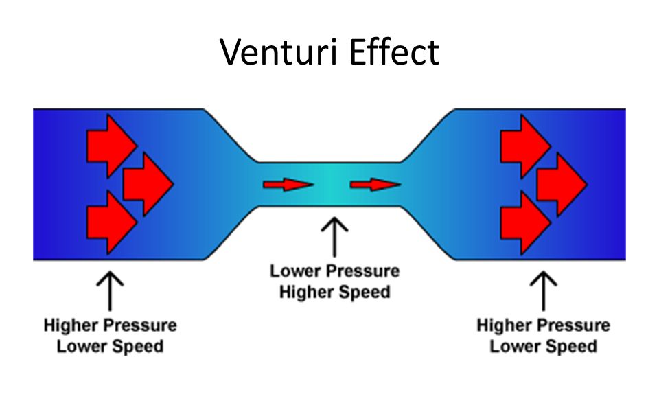
An important application of Bernoulli's theorem is called a Venturi tube, which consists of a horizontal tube that has been narrowed gradually, whose practical application is the measurement of the fluid velocity in a pipe.
It bears the name of its discoverer, the physicist Giovanni Battista Venturi, and its operation has much to do with the Bernoulli Principle, another physicist, in this Swiss case, which roughly explains to us that throughout a duct, an ideal fluid (without viscosity or friction), keeps the same energy at all times.
But back to the Venturi, what is it based on? Imagine that we have a tube through which a fluid circulates. In one of its sections, there is a narrowing. Well, in the interval of time that passes through that area, the fluid will do so at a higher speed and exerting less pressure than when it does it through the "normal" part of the conduit. If in that thinnest section we made a graft with another tube, we could check that there would be a suction towards the main conduit.

Source
The Venturi tube
A Venturi tube is a device initially designed to measure the velocity of a fluid. However, some are used to accelerate the velocity of a fluid by forcing it to pass through a narrow tube in the shape of a cone. The classic application of speed measurement of a fluid consists of a tube formed by two conical sections joined by a narrow tube in which the fluid moves consequently at a higher speed. The pressure in the Venturi tube can be measured by a U-shaped vertical tube connecting the wide region and the narrow channel. The difference in liquid heights in the U-tube makes it possible to measure the pressure at both points and consequently the speed. When using a Venturi tube, a phenomenon called cavitation must be taken into account. This phenomenon occurs if the pressure in some section of the tube is less than the vapor pressure of the fluid. For this particular type of tube, the risk of cavitation is in the throat of the same, since here, as the area is minimal and the speed is maximum, the pressure is the lowest that can be found in the tube. When cavitation occurs, bubbles are generated locally, which travel along the tube. If these bubbles reach areas of higher pressure, they can collapse thus producing local pressure peaks with the potential risk of damaging the tube wall.
Source
Operation of a venturi tube
The Venturi Tube is a device that causes a loss of pressure when a fluid passes through it. In essence, this is a straight short pipe, or throat, between two conical sections. The pressure varies in the vicinity of the narrow section; thus, when placing a manometer or recording instrument in the throat, the pressure drop can be measured and the instantaneous flow can be calculated, or, joining it to a fuel tank, this fuel can be introduced into the main stream.
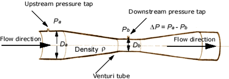
The dimensions of the Venturi Tube for flow measurement, as established by Clemens Herschel, are usually those indicated in Figure 1. The inlet is a straight short pipe of the same diameter as the pipe to which it is attached.
The entrance cone, which forms the angle a1, leads through a smooth curve to the throat of diameter d1. A long divergent cone, which has an angle a2, restores the pressure and expands the fluid to the full diameter of the pipe. The diameter of the throat varies from one third to three quarters of the diameter of the pipe.
Source
The pressure that precedes the inlet cone is transmitted through multiple openings to an annular opening called piezometric ring. Similarly, the pressure in the throat is transmitted to another piezometric ring. A single pressure line exits each ring and is connected to a pressure gauge or recorder. In some designs the piezometric rings are replaced by simple pressure joints leading to the inlet pipe and throat.
The main advantage of the Venturi is that it only loses 10 - 20% of the pressure difference between the entrance and the throat. This is achieved by the divergent cone that decelerates the current.
It is important to know the relationship that exists between the different diameters that the tube has, since depending on them it is that the desired pressure will be obtained at the entrance and exit of the same so that it can fulfill the function for which it is built. This ratio of diameters and distances is the basis to perform the calculations for the construction of a Venturi Tube and with the knowledge of the flow that you want to pass through it.
Deducting it can be said that a typical Venturi Tube consists, as already mentioned, of a cylindrical intake, a convergent cone, a throat and a divergent cone. The convergent entrance has an included angle of around 21º, and the divergent cone of 7º to 8º. The purpose of the divergent cone is to reduce the overall loss of pressure in the meter; its elimination will have no effect on the discharge coefficient. Pressure is detected through a series of holes in the admission and throat; these holes lead to an angular chamber, and the two chambers are connected to a pressure differential sensor.
In the Venturi Tube the flow from the main pipe in section 1 is accelerated through the narrow section called throat, where the fluid pressure decreases. The flow is then expanded through the diverging portion to the same diameter as the main pipe. In the wall of the pipe in section 1 and in the wall of the throat, which we will call section 2, are located pressure ramifiers. These are attached to the two sides of a differential pressure gauge in such a way that the deflection h is an indication of the pressure difference p1 - p2. Of course, other types of differential pressure gauges can be used.
The energy equation and the continuity equation can be used to derive the relationship through which we can calculate the velocity of the flow. Using sections 1 and 2 in formula 2 as reference points, we can write the following equations:
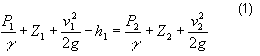 (1)
(1)
Q = A1v1 = A2v2 (2)
These equations are valid only for incomprehensible fluids, in the case of liquids. For the flow of gases, we must pay special attention to the variation of specific weight with pressure. The algebraic reduction of equations 1 and 2 is as follows:
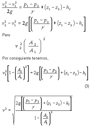
Two simplifications can be carried out at this time. First, the difference in elevation (z1-z2) is very small, even when the meter is installed vertically. Therefore, this term is despised. Second, the term hl is the loss of fluid energy as it flows from section 1 to section 2.
The hl value must be determined experimentally. But it is more convenient to modify the equation (3) by eliminating h1 and introducing a discharge coefficient C:
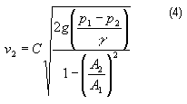
Equation (4) can be used to calculate the flow velocity in the throat of the meter. However, it is usually desired to calculate the volume flow rate. Since, we have:
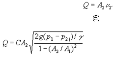
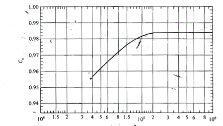
The value of the coefficient C depends on the Reynolds number of the flow and the actual geometry of the meter. The following figure shows a typical curve of C Vs Reynolds number in the main pipe.
Source
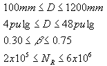
Reference 3 recommends that C = 0.984 for a Venturi pipe manufactured or cast with the following conditions:
Technological aplications of a venturi tube
The Venturi Tube can have many applications among which we can mention:
- In the Automotive Industry:
In the car's carburetor, the use of it can be observed in what is Fuel Fuel. The engines require air and fuel to operate. A liter of gasoline needs approximately 10,000 liters of air to burn, and there must be some metering mechanism that allows the mixture to enter the engine in the correct proportion. This doser is called a carburetor, and is based on the Venturi principle: by varying the inside diameter of a pipe, the speed of the air passage is increased.

Source
- Orifice plate:
When said plate is placed concentrically within a pipe, it causes the flow to contract suddenly as it approaches the hole and then suddenly expands to the total diameter of the pipe. The current flowing through the orifice forms a contracted vein and the rapid velocity of the flow results in a downward pressure decrease from the orifice.
The actual value of the discharge coefficient C depends on the location of the pressure ramifications, it is also affected by variations in the geometry of the edge of the hole. The value of C is much lower than that of the venturi tube or the flow nozzle since the fluid is forced to perform a sudden contraction followed by a sudden expansion.
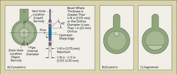
Some types of orifice plates are the following:
Source
The concentric serves for liquids, the eccentric for the gases where the changes of pressure imply condensation, when the fluids contain a high percentage of dissolved gases.
The great advantage of the orifice plate in comparison with the other primary elements of measurement, is that due to the small amount of material and the relatively short time of machining required in its manufacture, its cost becomes comparatively low, apart that it is easily reproducible, easy to install and dismantle and that a high degree of accuracy is achieved with it. In addition, it does not retain many particles suspended in the fluid inside the hole.
The use of the orifice plate is inadequate in the measurement of fluids with solids in suspension because these particles can accumulate in the entrance of the plate. The behavior in its use with viscous fluids is erratic since the plate is calculated for a temperature and a given viscosity and produces the highest pressure losses compared to the other primary elements.
The biggest disadvantages of this meter are its limited capacity and the loss of load caused by both the waste fluid and the energy losses that occur when vortices are formed at the outlet of the hole.
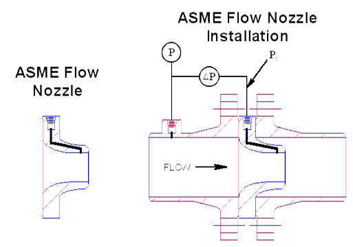
- Floz nozzle:
It is a gradual contraction of the flow stream followed by a straight and short cylindrical section. Due to the even and gradual contraction, there is a very small loss. At large values of Reynolds (106) C is greater than 0.99. The flow nozzle is a measuring instrument that allows differential pressure measurement when the ratio of ß is too high for the orifice plate, that is, when the flow velocity is much higher and the losses begin to become noticeable. Then, when installing a meter of this type much more accurate measurements are achieved. In addition this type of meter is useful for fluids with many particles in suspension or sediments, its hydrodynamic shape prevents sediments transported by the fluid to adhere to the nozzle.
Source
The installation of this meter requires that the pipeline where the flow is to be measured, is in a straight line regardless of the orientation it has.
- Pressure recovery:
The pressure drop is proportional to the loss of energy. The careful alignment of the Venturi tube and long gradual expansion after the throat causes a very small excess of turbulence in the flow stream. Therefore, the energy loss is low and the pressure recovery is high. The lack of a gradual expansion causes the nozzle to have a lower pressure recovery, while the one corresponding to the orifice is even lower. The best pressure recovery is obtained in the flow tube.
Greetings!
For more information visit the following links.
I'm an instrumentation technician. We use venturi tubes, orifice plates and flow nozzles for flow measurement. Most of the equipment I've worked with applies to the oil and gas industry.
It's good to see some STEM posts popping up. I rarely see anything that has to do with my line of work. Nice post.
This post most have taken a ton of time. Here is a tip: if you want to get upvoted by steemstem, you should cite your sources. Here is a link to the steemstem guidelines.
https://steemit.com/steemstem/@steemstem/being-a-member-of-the-steemstem-community
Hope this helps you get discovered. Cheers!