Sign In
Upload
Manuals
Brands
Sun Microsystems Manuals
Server
Sun Enterprise 4500
Sun Microsystems Sun Enterprise 4500 Manuals
Manuals and User Guides for Sun Microsystems Sun Enterprise 4500. We have
4
Sun Microsystems Sun Enterprise 4500 manuals available for free PDF download: Reference Manual, Installation Manual
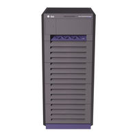
Sun Microsystems Sun Enterprise 4500 Reference Manual (304 pages)
Brand:
Sun Microsystems
| Category:
Storage
| Size: 3.97 MB
Table of Contents
Table of Contents
3
Figures
13
Preface
23
Product Overview
27
Standard Features
27
Enterprise 6500 and 5500 Systems
28
FIGURE 1-1 Front Views of the Sun Enterprise 6500/5500 and 4500 Servers
28
Figure
29
FIGURE 1-3 Rear View of the Enterprise 6500 System Cabinet
30
Enterprise 4500 System
31
FIGURE 1-4 Bezels for Enterprise 6500/5500 System - Two Examples
31
Definitions of Terms
32
TABLE 1-1 Definitions of Terms
32
Internal Options
33
TABLE 1-2 Internal Options for the Sun Enterprise Server Systems
34
Safety Precautions
35
Safety Precautions and Tools Requirements
35
FIGURE 2-1 Symbols, Part
36
Symbols
36
System Precautions
37
Tools Required
38
Cpu/Memory+ Boards and Components
39
TABLE 2-1 Safety Precautions
39
Handling Boards and Assemblies
40
FIGURE 3-1 Filler Panel (Enterprise 5500/4500 Only)
41
Filler Panels and Load Boards
41
FIGURE 3-2 Load Board (Enterprise 6500 Systems Only)
42
Hot-Plug Feature
42
Cpu/Memory+ Boards
43
Removing a Board
43
FIGURE 3-3 Unlocking and Locking Quarter-Turn Access Slots
44
FIGURE 3-4 Cpu/Memory+ Board
44
Installing a Board
45
FIGURE 3-5 Enterprise 6500 Board Locations
46
FIGURE 3-7 Board Replacement
48
Ultrasparc II Modules
49
FIGURE 3-8 Ultrasparc II Module Connectors
50
Handling Precautions
50
FIGURE 3-9 Ultra SPARC Module Connector Detail
51
FIGURE 3-10 Ultrasparc II Module Removal and Replacement
52
FIGURE 3-11 Tightening Compression Connector Screws
54
Memory Modules (Simms)
54
FIGURE 3-13 Ejecting a SIMM
56
FIGURE 3-14 Orienting a SIMM
58
FIGURE 3-15 Installing a SIMM
58
I/O+ Boards and Components
59
Handling Boards and Assemblies
60
FIGURE 4-1 Filler Panel (Enterprise 5500/4500 Only)
61
Filler Panels and Load Boards
61
FIGURE 4-2 Load Board (Enterprise 6500 System Only)
62
FIGURE 4-3 SCSI Terminator
62
SCSI Termination
62
Hot-Plug Feature
63
FIGURE 4-4 Sbus+ I/O Board with 100 Mb/Sec Fibre Channel
64
Gbic
64
I/O+ Boards
64
FIGURE 4-5 Graphics+ I/O Board with 100 Mb/Sec Fibre Channel
65
Removing a Board
66
FIGURE 4-7 Unlocking and Locking Quarter-Turn Access Slots
67
FIGURE 4-8 Extraction Lever in Extract Position
68
Installing a Board
69
FIGURE 4-9 Enterprise 6500 Board Locations
70
FIGURE 4-10 Enterprise 5500/4500 Board Locations
71
FIGURE 4-11 Board Replacement
72
FIGURE 4-12 Sbus+ I/O Board Sbus Card Connectors
74
FIGURE 4-13 Graphics+ I/O Board Sbus Card Connectors
74
Sbus Cards
74
FIGURE 4-14 Locking and Unlocking Standoffs
75
FIGURE 4-15 Removing or Installing an Sbus Card
76
FIGURE 4-18 DSBE/S Sbus Card
79
FIGURE 4-19 FSBE/S Sbus Card
79
FIGURE 4-20 Disabling and Enabling the Link Integrity Test
80
FIGURE 4-21 Graphics (UPA) Card Connector Location
81
Graphics (UPA) Cards
81
FIGURE 4-22 Removing or Installing a Graphics (UPA) Card
82
FIGURE 4-23 Sbus+ I/O Board GBIC Connector Locations
84
Gbics
84
FIGURE 4-24 Graphics+ I/O Board GBIC Connector Locations
85
FIGURE 4-25 Removing or Installing a GBIC
86
PCI Cards
87
FIGURE 4-26 PCI and Riser Card Removal
88
FIGURE 4-27 PCI Card Removal
89
FIGURE 4-28 JTAG Test Jumper
90
FIGURE 4-29 PCI Card Installation/Replacement
91
Disk Boards and Components
95
Handling Boards and Assemblies
96
FIGURE 5-1 Filler Panel (Enterprise 5500/4500 Only)
97
Filler Panels and Load Boards
97
FIGURE 5-2 Load Board (Enterprise 6500 Systems Only)
98
FIGURE 5-3 SCSI Terminator
98
SCSI Termination
98
Hot-Plug Feature
99
Disk Boards
100
Removing a Board
100
FIGURE 5-4 Unlocking and Locking Quarter-Turn Access Slots
101
FIGURE 5-5 Disk Board
101
Installing a Board
102
FIGURE 5-7 Board Replacement
104
Disk Drives
106
FIGURE 5-8 Disk Drive with Ejector Drive Retainer Open
107
Clock+ Board
109
Handling Boards and Assemblies
109
Clock+ Board
110
Clocks
112
Consolebus
112
Reset Logic
112
FIGURE 6-2 Clock+ Board
113
Removing a Clock+ Board
113
Installing a Clock+ Board
114
Power Supplies
115
Safety Precautions
116
TABLE 7-1 Power Supply Summary
116
TABLE 7-2 Safety Precautions
116
FIGURE 7-1 Peripheral Power Supply
117
Peripheral Power Supply
117
Power Distribution
117
FIGURE 7-2 Quarter-Turn Access Slot
118
Replacing a Peripheral Power Supply
118
Troubleshooting a Peripheral Power Supply
118
FIGURE 7-3 Replacing the Enterprise 6500/5500 PPS
119
FIGURE 7-4 Replacing the Enterprise 4500 PPS
120
Figure 7-5 Pcm
122
Power/Cooling Module (PCM)
122
Requirements for Redundant Power
122
Cooling Requirements
123
Replacing a PCM
124
Troubleshooting a PCM
124
Device Locations
129
Internal SCSI and Storage Devices
129
FIGURE 8-1 Enterprise 6500 System Storage Device Locations
130
FIGURE 8-2 Enterprise 5500 System Storage Device Locations
131
FIGURE 8-3 Enterprise 4500 System CD-ROM and Tape Drive Locations
132
Tape and CD-ROM Drives
132
Use and Maintenance
132
Enterprise 6500/5500 Tape or CD-ROM Drive
133
FIGURE 8-4 Removing the Top Front Panel
133
FIGURE 8-5 CD-Rom/Tape Drive Removal and Replacement
134
Enterprise 4500 Tape or CD-ROM Drive
135
FIGURE 8-6 Removing the Front Panel Bezel
135
FIGURE 8-7 Removing and Replacing the Media Tray
136
Disk Drives
138
Sun Storedge Flexipack Tray
138
Troubleshooting Overview
139
Using a Terminal
139
Hardware Indicator Leds
141
Clock+ Board Leds
142
System Front Panel Leds
142
TABLE 9-1 System Status Codes
142
Cpu/Memory+ and I/O+ Board Leds
143
TABLE 9-2 Board Status LED Codes
143
Basic Troubleshooting for Boards
144
Disk Board Leds
144
Power Supplies
144
Disk Tray Indicators
145
Diagnosing Problems
146
Error Messages
146
Prtdiag(1M)
146
Sunvts
146
POST and Openboot
147
Solstice Symon
148
Failure of Network Communications
149
Specific Problems and Solutions
149
Resetting and Power Cycling the System from a Remote Console
151
TABLE 9-4 Remote Console Commands
151
Flow Diagrams for Troubleshooting
153
No AC or DC Power
154
System Cannot Boot
155
Defective Cpu/Memory+ Board
156
Defective I/O+ Interface Board
157
Defective Disk Board
158
Defective Disk Drive
159
Defective Power Supplies
160
Defective Clock+ Board
161
Network Does Not Respond
162
Powering off and on
163
Powering off the System
163
FIGURE 1-5 Enterprise 4500 System
165
TABLE 11-1 LED Status Indicators
171
TABLE A-3 Enterprise 6500/5500 Shipping Specifications
186
TABLE A-4 Enterprise 4500 Physical Specifications
186
TABLE A-5 Enterprise 4500 Clearance and Service Access
186
TABLE A-6 Enterprise 4500 Shipping Specifications
186
TABLE A-10 Enterprise 4500 Temperature, Humidity, and Altitude Limits
188
TABLE A-9 Enterprise 6500/5500 Temperature, Humidity, and Altitude Limits
188
FIGURE B-2 Sun Enterprise System Cabinet
192
FIGURE B-3 Enterprise 5500 Server
193
FIGURE B-4 Enterprise 4500 Standalone Server
194
FIGURE B-5 Cpu/Memory+ Board
196
FIGURE B-6 SIMM Slot Locations
198
FIGURE 4-6 PCI+ I/O Board
202
FIGURE B-9 PCI+ I/O Board
202
Figure B-10 Pcm
204
FIGURE B-11 Peripheral Power Supply
205
FIGURE B-12 Clock+ Board
206
TABLE C-1 Media Tray Default SCSI ID Numbers
209
TABLE C-2 Disk Board Default SCSI Disk Drive ID Numbers
210
TABLE D-1 Example of CPU Placement
216
TABLE E-1 List of Field Replaceable Units
219
FIGURE E-1 Replacing the Fan Tray Assembly in the Enterprise 6500/5500 Systems
220
FIGURE E-2 Opening the Power Connector Cover
222
FIGURE E-4 Replacing the Fan in the Media Tray in the Enterprise 6500/5500 Systems
225
FIGURE E-5 Removing the Front Bezel
226
FIGURE E-6 Removing the Cable Assemblies from the Front of the SCSI Adapter Tray
227
FIGURE E-7 Removing the Two Screws that Attach the Media Tray to the Flange
229
FIGURE E-8 Removing the Two Screws that Attach the Media Tray to the Cabinet Pillar
230
FIGURE E-9 Removing the Screw from the Left Pillar
231
FIGURE E-10 Removing the Two Screws from the Right Pillar
232
FIGURE E-11 Replacing the Key Switch Assembly in the Enterprise 6500/5500 Systems
233
FIGURE E-12 Removing the SCSI Tape Adapter PCS Assembly in the Enterprise 6500/5500 Systems
235
FIGURE E-13 Removing the 200/240V Fan Tray Assembly
237
FIGURE E-14 Removing the Fan Tray from the Enterprise 4500 System
242
FIGURE E-15 Removing the Top Bezel
244
FIGURE E-17 Removing the Media Tray
247
FIGURE F-1 Enterprise 6500 System, Front View
253
FIGURE F-2 Enterprise 6500 System, Rear View
254
FIGURE F-3 SCSI Tape Adapter PCS Assembly
255
FIGURE F-4 Key Switch Tray
255
FIGURE F-6 Power Sequencer
257
FIGURE F-7 Fan Tray Assembly
258
FIGURE F-8 Centerplane Assembly
259
FIGURE F-9 Power/Cooling Module (PCM
259
FIGURE F-10 Peripheral Power Supply
260
FIGURE F-11 Cpu/Memory+ Board
261
FIGURE F-12 Sbus+ I/O Board Assembly
262
FIGURE F-13 Graphics+ I/O Board Assembly
263
FIGURE F-14 PCI+ I/O Board Assembly
264
FIGURE F-15 Clock+ Board Assembly
265
FIGURE F-16 Disk Board Assembly
266
FIGURE F-17 Load Board Assembly
267
FIGURE F-18 Enterprise 4500 System, Front View
268
FIGURE F-21 Fan Tray Assembly
270
FIGURE F-22 Centerplane Assembly
270
Connectors
273
Centerplane Connector
274
Cpu/Memory+ Board
274
FIGURE G-1 Cpu/Memory+ Board Connector Locations
274
CPU Module Connectors
276
FIGURE G-4 CPU Module 0 Connector (144 Pin) Location
276
FIGURE G-5 CPU Module 1 Connector (144 Pin) Location
276
FIGURE G-6 CPU Module 0 Connector (288 Pin) Location
276
FIGURE G-7 CPU Module 1 Connector (288 Pin) Location
276
Centerplane Connector
278
FIGURE G-10 PCI+ I/O Board Connector Location
278
FIGURE G-11 I/O+ Board Sbus 0 Connector Locations
279
FIGURE G-12 I/O+ Board Sbus 1 Connector Location
279
Sbus Connectors
279
FIGURE G-13 I/O+ Board Sbus 2 Connector Locations
280
FIGURE G-14 Graphics+ I/O Board UPA Connector Location
280
UPA Connector Location
280
Ethernet Connector (TPE)
281
MII Connector
281
FIGURE G-17 I/O+ Board GBIC 0 Connector Locations
282
FIGURE G-18 I/O+ Board GBIC 1 Connector Locations
282
GBIC Connectors
282
PCI Connectors
283
SCSI Connector
283
Centerplane Connector
284
Disk Board
284
FIGURE G-21 Disk Board Connector Locations
284
FIGURE G-22 Disk Board Centerplane Connector Location
284
FIGURE G-23 Disk Board SCSI in Connector Location (Upper
285
FIGURE G-24 Disk Board SCSI out Connector Location (Lower
285
SCSI in Connector
285
SCSI out Connector
285
Clock+ Board
286
FIGURE G-25 Clock+ Board Connector Locations
286
Centerplane Connector
287
FIGURE G-26 Clock+ Board Centerplane Connector Location
287
Serial Port Connectors
288
FIGURE G-29 Clock+ Board Keyboard/Mouse Connector Location
289
FIGURE G-30 Keyboard and Mouse Connector Pinouts
289
Keyboard and Mouse Connector
289
Advertisement
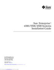
Sun Microsystems Sun Enterprise 4500 Installation Manual (76 pages)
Brand:
Sun Microsystems
| Category:
Server
| Size: 0.93 MB
Table of Contents
Installation Guide
1
Table of Contents
3
Typographic Conventions
12
Related Documentation
13
Sun Welcomes Your Comments
14
1 Preparing for Installation
17
FIGURE 1-1 Enterprise 6500/5500/4500 Systems
17
Unpacking the Enterprise 6500/5500 Cabinet Systems
18
Shipping and Storing the System
20
FIGURE 1-2 Attaching the Ramps to the Shipping Pallet
20
Preparing the Electrical Circuits
21
Enterprise 6500/5500 Cabinet Systems
21
Enterprise 4500 System
22
Preparing the Air Conditioning
22
Preparing the Ethernet Network
23
FIGURE 1-4 Example of 10/100BASE-T (Twisted-Pair) Ethernet
24
Preparing the Area
25
Enterprise 6500/5500 Cabinet Systems
25
Enterprise 4500 System
26
Preparing the Enterprise 6500/5500 Cabinet Systems
27
Moving the Server
27
Adjusting the Levelling Pads
28
FIGURE 1-7 Moving the Server Safely down the Ramps
28
FIGURE 1-8 Levelling Pad
29
Adding Storage Devices
30
FIGURE 1-9 Stabilizer Bar
30
Preparing the Enterprise 4500 System
31
Using the User Naming Area
31
2 Cabling the System
33
Preparing the System for Cabling
33
Removing and Replacing the Enterprise 6500/5500 Cabinet Rear Door and Kick Panel
33
Removing the Rear Door and Kick Panel
33
FIGURE 2-1 Key Switch Standby Position
34
FIGURE 2-2 AC Power Sequencer Power Switch
34
Replacing the Rear Door and Kick Panel
35
Connecting the Power Cords
35
Enterprise 6500/5500 System Power Cord
35
Enterprise 4500 System Power Cord
36
FIGURE 2-3 Key Switch Positions
36
FIGURE 2-4 AC Power Switch and Power Receptacle
36
Connecting the Network Cable to the System
37
FIGURE 2-5 Network Cable
37
Connecting the System to the Network
38
FIGURE 2-6 10/100BASE-T Ethernet Connection
38
Connecting an ASCII Terminal
41
FIGURE 2-9 Clock+ Board
41
Connecting the Fiber Cable to the I/O+ Board
42
FIGURE 2-10 Fiber Cable and Fiber Card Connectors and Ports on the I/O+ Board
43
Connecting External SCSI Devices
44
3 Powering the System on and off
47
Using Jumpstart Automatic Installation
47
Enterprise 6500/5500 Cabinet Systems
48
Powering on the System
48
Reading Boot Messages
52
Interpreting Status LED Patterns
53
Powering off the System
54
Enterprise 4500 System
55
Powering on the System
55
Reading Boot Messages
58
Interpreting Status LED Patterns
59
Powering off the System
60
Failure of Network Communications
61
4 Software
63
Operating System Software and Patches
63
Sun™ Management Center Software
63
Dynamic Reconfiguration for Hot-Pluggable System Boards
64
CPU Over-Temperature Safeguard (COS)
64
Regulatory Agency Compliance Statements
65
FCC Class a Notice
66
FCC Class B Notice
67
DOC Class a Notice - Avis DOC, Classe a
68
DOC Class B Notice - Avis DOC, Classe B
68
BSMI Class a Notice
69
Declaration of Conformity
70
Supplementary Information
70
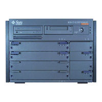
Sun Microsystems Sun Enterprise 4500 Installation Manual (12 pages)
for 464-MHz 8-Mbyte CPU Module
Brand:
Sun Microsystems
| Category:
Computer Hardware
| Size: 0.09 MB
Advertisement
Sun Microsystems Sun Enterprise 4500 Installation Manual (2 pages)
System EMI Spring Gasket
Brand:
Sun Microsystems
| Category:
Server
| Size: 0.11 MB
Advertisement
Related Products
Sun Microsystems Ultra Enterprise 450
Sun Microsystems Fire 4800
Sun Microsystems Fire 4810
Sun Microsystems Enterprise 420R
Sun Enterprise 4 00 Series
Sun Microsystems Sun Enterprise 4000
Sun Microsystems Sun Enterprise 10000 DR 2.0
Sun Microsystems Sun Enterprise 450
Sun Microsystems Sun Enterprise 220R
Sun Microsystems Sun Enterprise 10000
Sun Microsystems Categories
Server
Storage
Desktop
Computer Hardware
Adapter
More Sun Microsystems Manuals
Login
Sign In
OR
Sign in with Facebook
Sign in with Google
Upload manual
Upload from disk
Upload from URL