
The Construction of the Origami Level-n Menger Sponge Complement by the PJS Technique

Independent Researcher, 38122 Trento, Italy
Crystals 2021, 11(5), 468; https://doi.org/10.3390/cryst11050468
Submission received: 18 March 2021
/
Revised: 17 April 2021
/
Accepted: 19 April 2021
/
Published: 22 April 2021
(This article belongs to the Special Issue Crystalline Patterns as Bases for Design of Engineering Structures, Mechanisms and Metamaterials)
Abstract
:In 2015, the author developed a new origami technique, called PJS technique (where PJS stands for “pleat and join strips”), by which we can construct polycubes, that are polyhedrons composed of elementary cubes, called units, connected face to face. Each strip, pleated in squares, has to cover four faces of a tower of stacked units, called a segment, having as length the number of units that form the tower. Each unit is composed by weaving together three paper strips in the three spatial directions and the length of each strip depends on the length of the segment in each respective direction. The PJS technique allowed the author to build, at the end of 2016, the first specimen of a level-4 origami Menger sponge and three yeas later, the first level-3 complement model. In this paper, we give a formula to compute the number of segments that make up a level-n Menger sponge complement in all directions and consequently, the number of modules needed for each length to build this polycube with the PJS technique.
1. Introduction
There are many techniques to construct geometric objects in origami that have a very strong symmetry. As examples, we mention tesselations [1,2,3,4,5], polyhedra [6], and fractals [7,8]. Roughly, these can be divided into two groups: those that are made from a single piece of paper that is folded many times, and those that consist of many pieces of paper (called modules) that are folded and connected. The origami of the second type are called modular [9,10]. This paper is devoted to a recent modular origami technique for constructing polycubes, and in particular, modular fractal models.
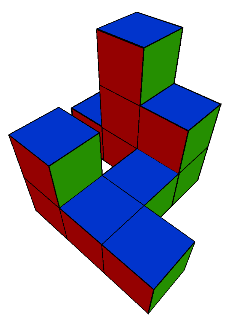
Polycubes are polyhedrons that are formed by joining one or more equal cubes, called units, face to face, as in Figure 1. Menger sponges of various levels and their complements are examples of polycubes.
There are several origami techniques for constructing polycubes. In particular, we mention the technique of Jeannine Mosey [11], based on the folding of business cards, by which the first specimen of a level-3 Menger sponge has been constructed. With this technique, as it involves connecting single cubes, it has not been possible to construct Menger sponges of levels higher than three, because the resulting cubes would collapse under their own weight.
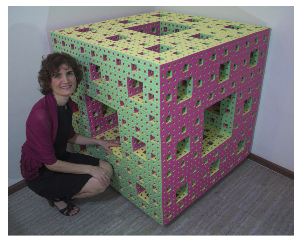
In order to overcome such problems of instability, in 2015, the author developed a technique, called the PJS technique (for “pleat and join strips”) published in [12], through which every unit cube is created by intertwining three paper strips in the three spatial directions. Thanks to this technique, on November 2016, the first specimen of a level-4 Menger sponge in the origami was completed (Figure 2).
In [12], it is shown how to decompose, with respect to a given spatial direction, the polycube in towers of unit cubes that are called segments. This division lies at the basis of the PJS technique because the lengths of the strips that are to be used vary and depend on the lengths of these segments. The Section 2 is dedicated to the PJS technique. In particular, in Section 2.1 we will describe the decomposition of polycubes into segments in a more graphical and less technical way as compared to [12] and in Section 2.2, we will recall how the PJS technique works, by constructing, unit by unit, the polycube in Figure 1.
The PJS technique is based on strips pleated in squares, called modules, in which the various lengths depend on the lengths of the various segments in which the structure is decomposed. It follows that it is necessary to count the number of segments for every length in the three spatial directions.
Thanks to their symmetry, the structure of the Menger sponges of various levels, and of their complements, can be analyzed by focusing on one of the spatial directions, yielding conclusions that are valid in general. The main result of the paper [12] shows how to count the number of modules that are necessary to realize a level-n Menger sponge with the PJS technique. This result will be recalled in Section 3.
Section 4 contains the main result of the present paper, that is, a general formula to compute the number of modules, for each length, that is necessary to construct the complement of a level-n Menger sponge using the PJS technique.
2. The PJS Technique
With the PJS technique, it is possible to realize polycubes. Every unit cube is created by intertwining three paper strips as illustrated in Figure 3.
Every strip, pleated in squares, has to contribute to the creation of a given segment in a given direction.
2.1. Segments of a Polycube
The paper [12] gives a technical and precise description of how a polycube can be divided into segments, with respect to the three spatial directions, so as to make it possible to determine the lengths of the modules and the number of modules of each length necessary to construct the polycube with the PJS technique. In this paper, we would like to provide a less technical but more graphical description of the technique.
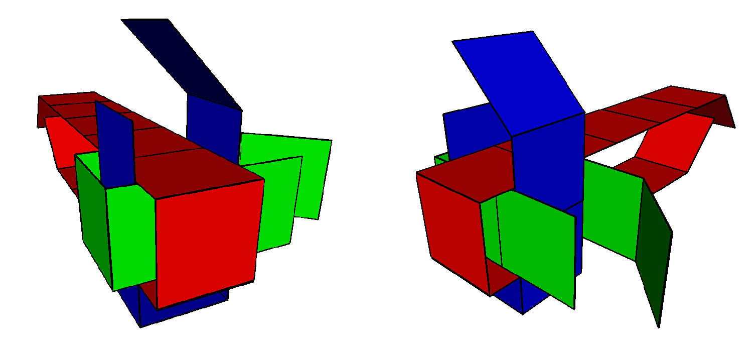
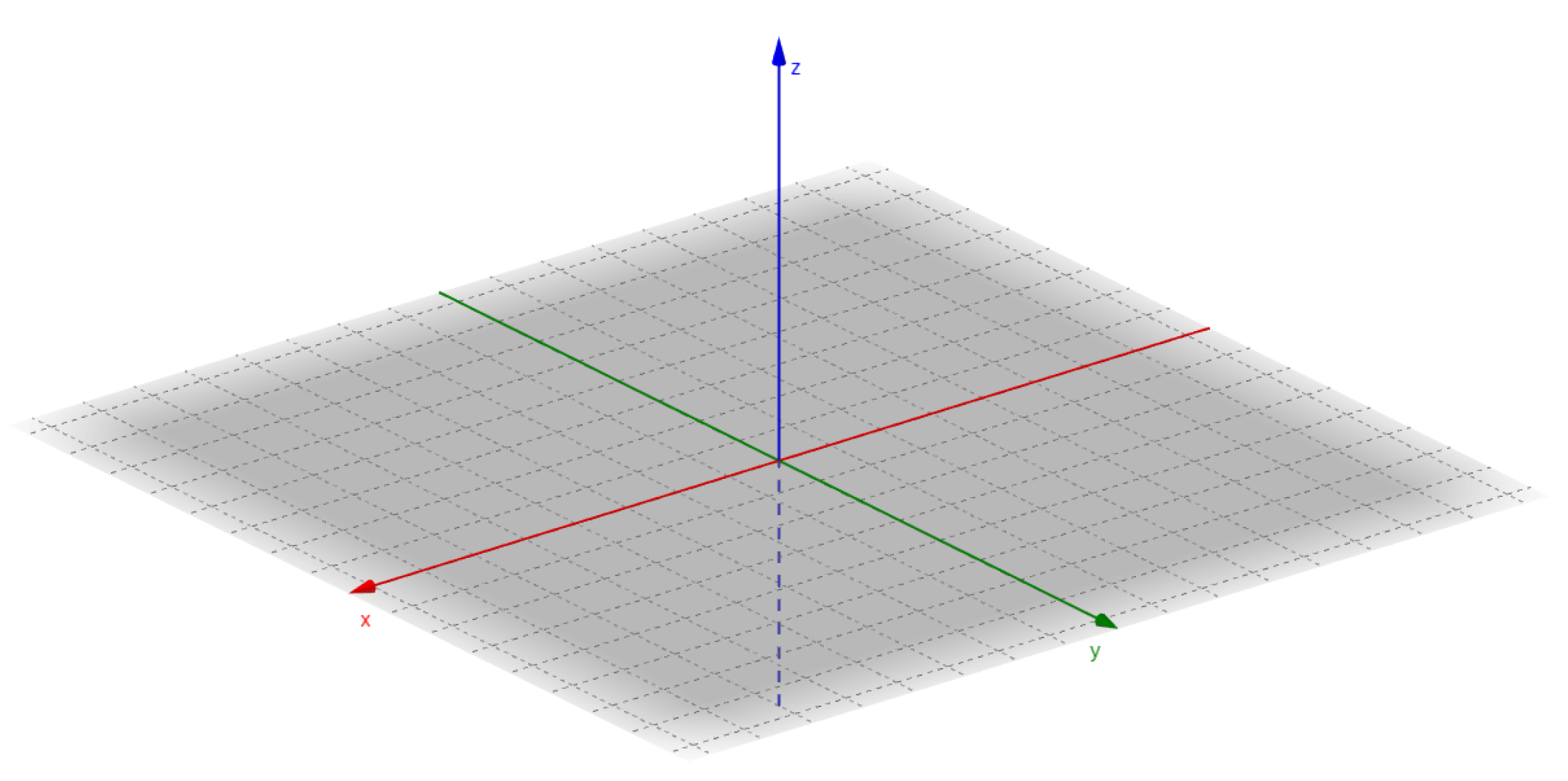
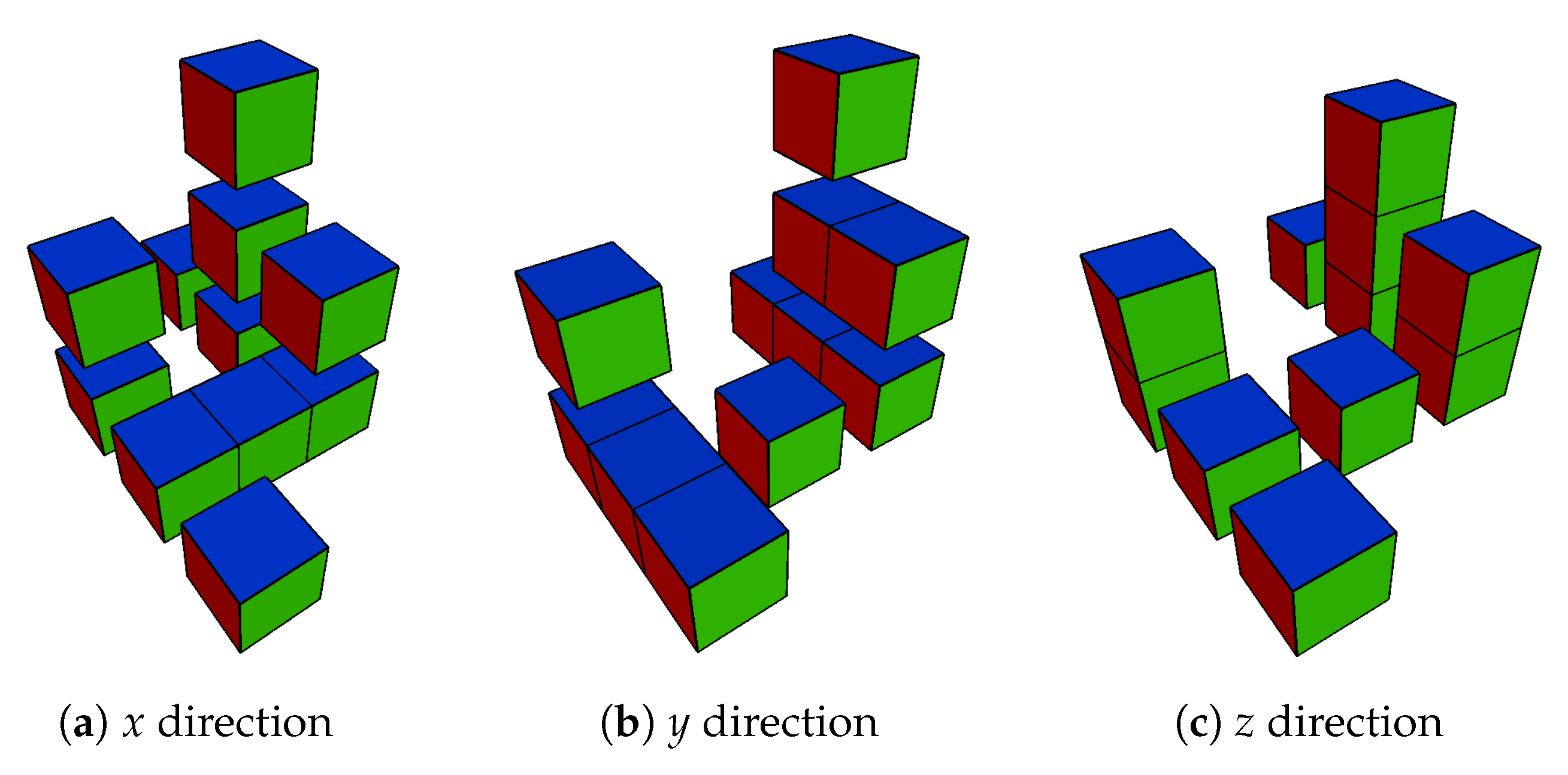
Let us observe our polycube from a specific direction and slice the structure virtually along the contact lines between the unit cubes along the chosen direction. As an example, we considered the polycube in Figure 1. Slicing it along each of the three spatial directions, by which, imagining it inside a cartesian space (as shown in Figure 4), we obtained the following three configurations (as shown in Figure 5).
For each direction, we constructed a table where in the first column, we indicated the length of the segment (that is, the number of unit cubes of which it is made) and in the second column, we displayed the number of segments having this length. For example, if we focus on segments consisting of three unit cubes, we observe that in the y direction, we have 2 of them and in the other two directions, there is only 1 of them. Analyzing all segments, we arrive at the Table 1.
2.2. The Technique
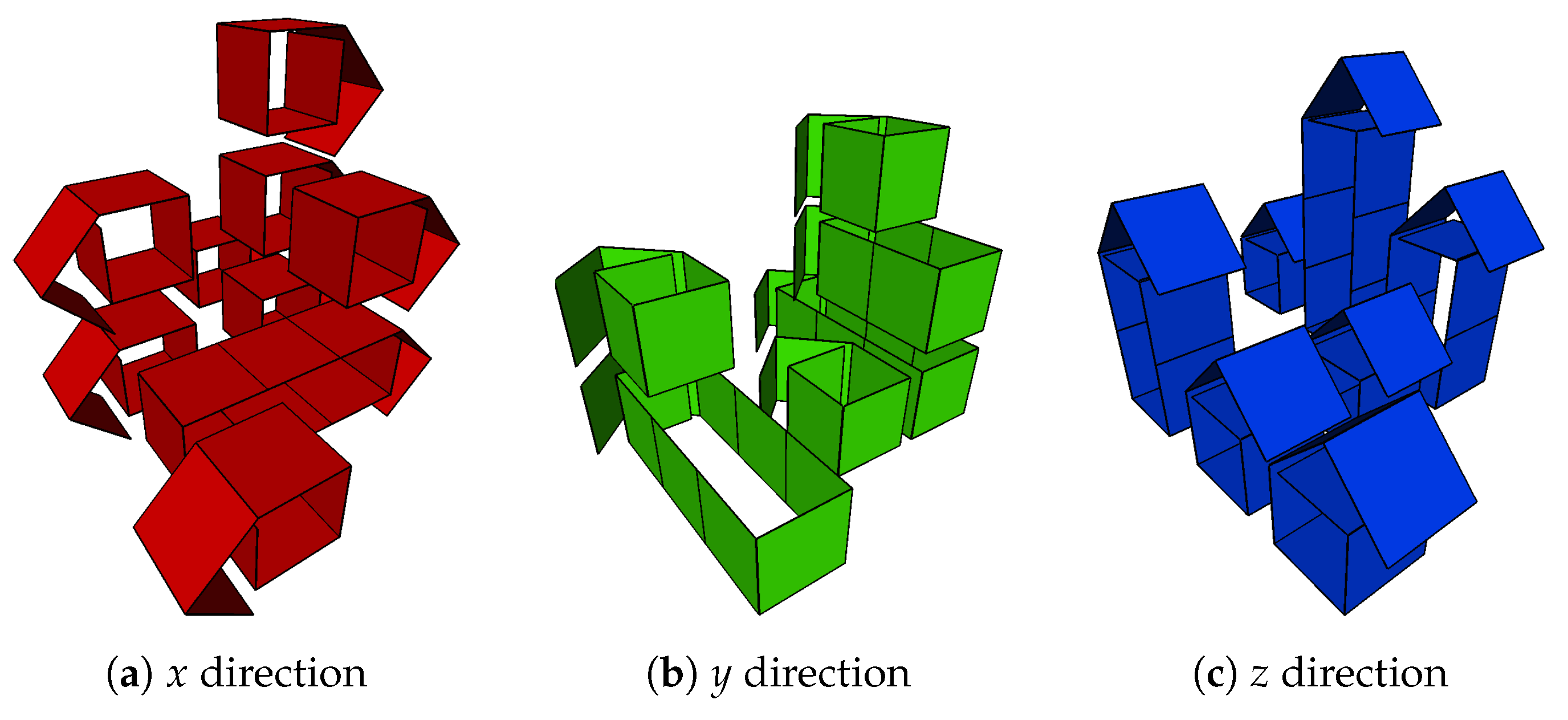
In the PJS technique, every strip, pleated in squares, has to contribute to the creation of a given segment in a given direction. If a segment in a direction has a length k, then we need a strip pleated in squares, called modules. Of the squares, are needed to surround four faces of the segment, starting with either the infimum or the supremum of the segment. The -rd square is superimposed on the first one at the base unit. The -th square forms the wing which will be inserted in the pocket created by one of the strips that contribute to the creation of the base unit in one of the other directions.
Considering the subdivision into segments shown in Figure 5, in order to construct the polycube in Figure 1, we need the modules that are shown in Figure 6. They match the entries in Table 1.
In particular, to cover the segments of length 3, we need modules of 10 squares, and for the segments of length 2, the modules have 8 squares and for the segments of length 1, we need modules of 6 squares.
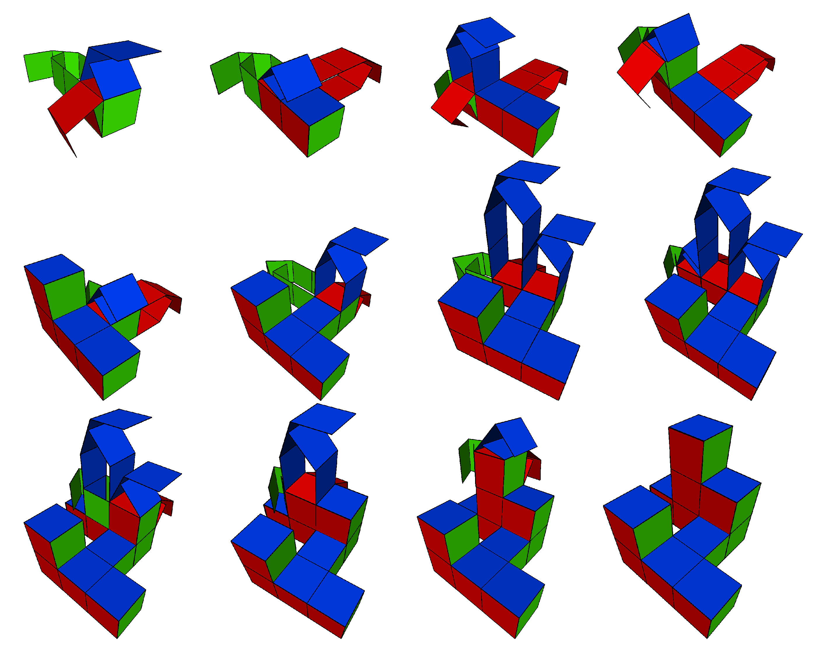
In Figure 7, we show the sequence of steps by which we form the 11 cubes of which the polycube in our example is composed.
For a more technical and complete description of the PJS technique, we refer to the paper [12].
3. Origami Menger Sponge Levels
We recall here the construction of the Menger sponge. A Menger sponge of the first level is obtained by dividing a cube into 27 smaller cubes after which the cube in the middle and those at the center of each face are removed (20 cubes remain). To obtain the second level we repeat the process with each new cube. Again, for the third level, we repeat it for all cubes of the second level, etc. Repeating this process infinitely eventually gives the Menger sponge fractal. By , we denote the level-n Menger sponge. See Figure 8 for the first three levels.
Thus, by construction, consists of 20 copies of , which are arranged as the 20 cubes that make up a Menger sponge of the first level. As shown in Section 4 of [12] all segments of a that enter into contact with segments of a consecutive have length a power of 3. In particular, all segments of length , with , that enter into contact with a segment of the same length in a consecutive form a segment consisting of unit cubes in . Furthermore, those of length will be joined to two other segments to form a segment of length that traverses three copies of a . It follows that the segments that are present in an consist of unit cubes for , or of unit cubes with .
The number of segments of each length are summarized in the next theorem that is proved in [12].
Theorem 1.
The level-n Menger sponge is formed, in every direction, of:
- segments of length ;
- segments of length for every ;
- segments of length for every .
Example 1.
The number of segments of a level-4 Menger sponge, in each direction, along with their lengths, is given in Table 2:
4. Constructing Level- Menger Sponge Complement
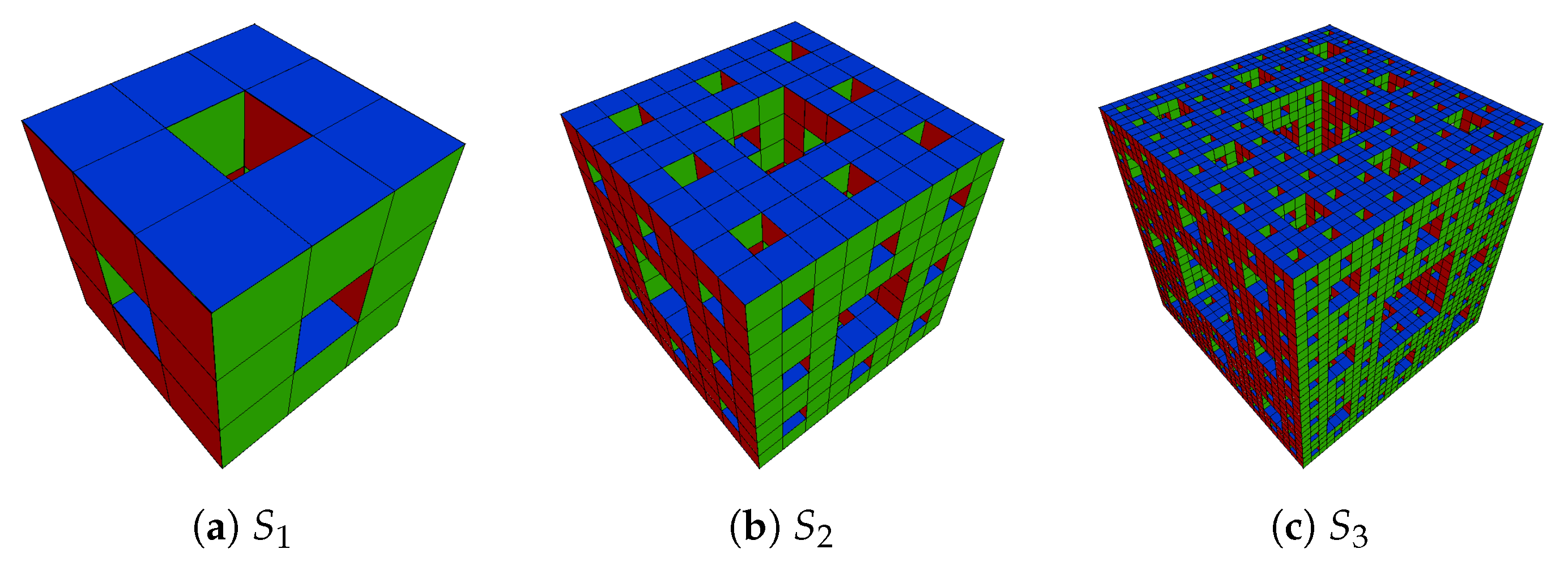
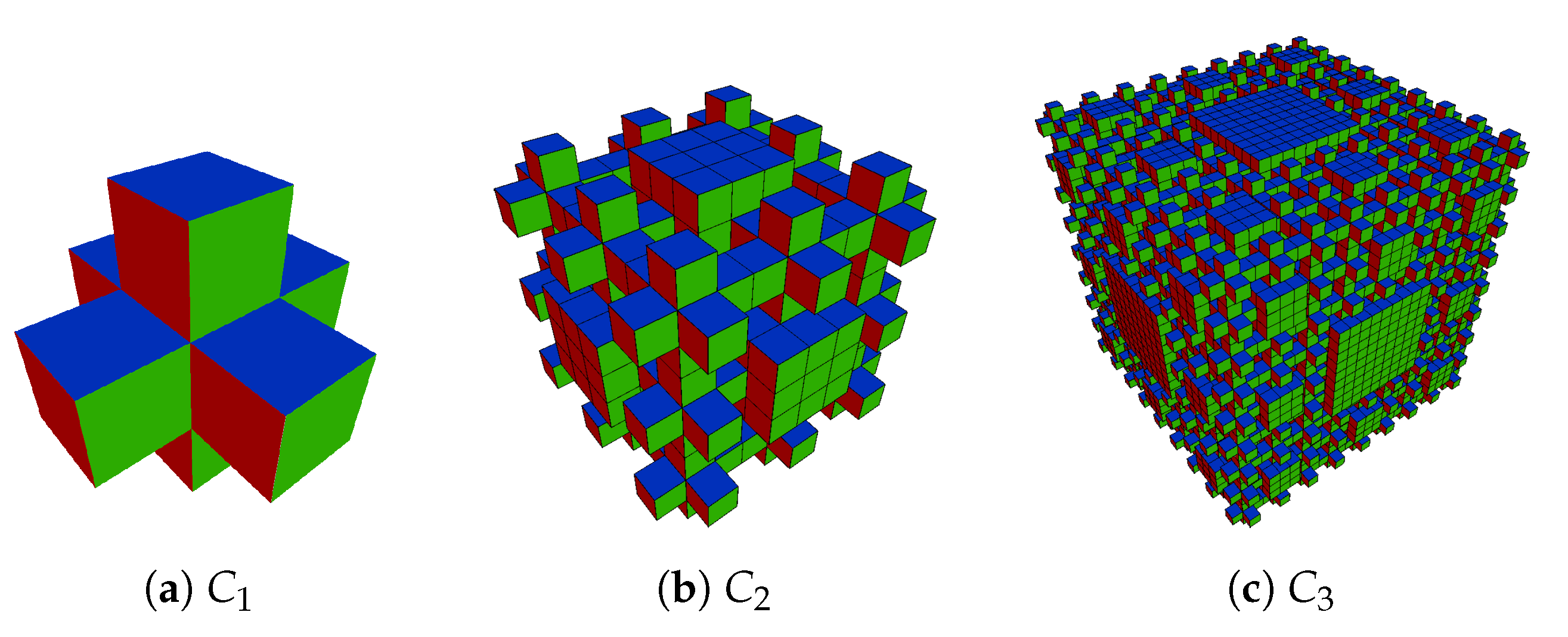
For each level-n Menger sponge , we can consider its complement, that is the set of integer cubes that do not belong to the structure of . With , we denote the polycube that is the complement to , as can be seen Figure 9 for the first three levels.
Furthermore, by , we denote the cube composed of unit cubes, that is the cube whose sides consist of unit cubes.
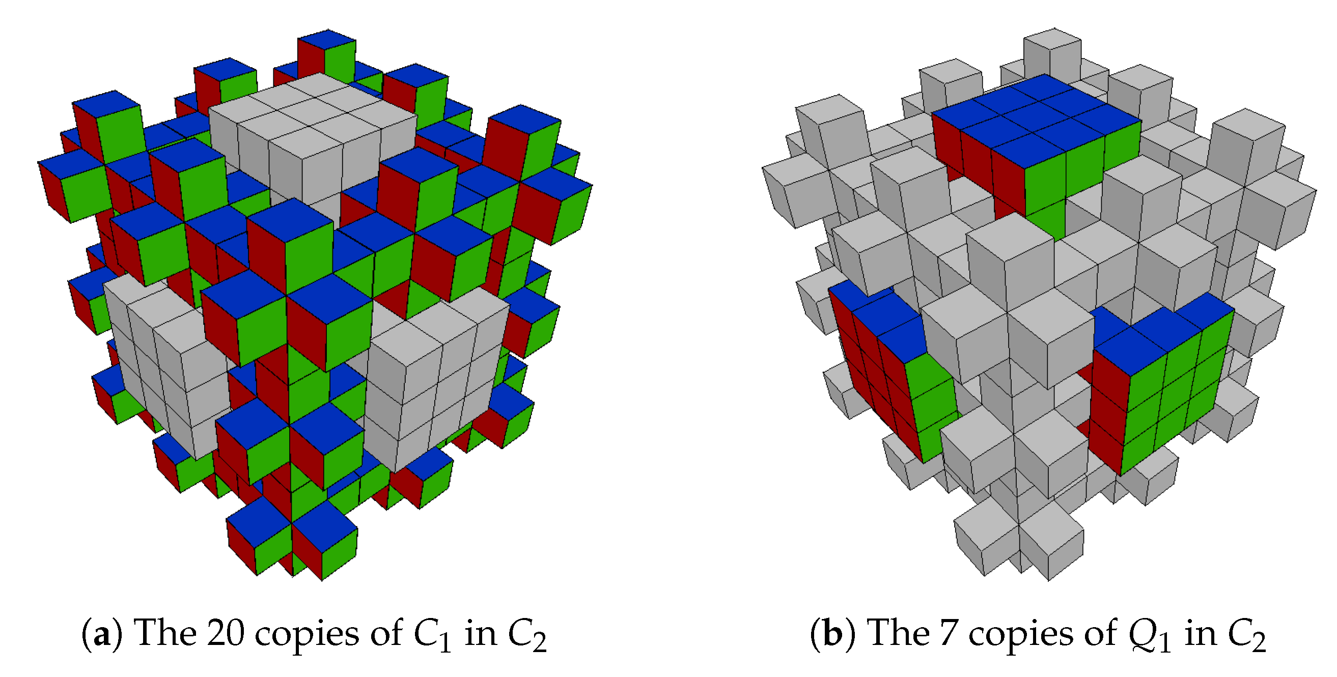
By construction, consists of 20 copies of that are arranged as the unit cubes of an , along with 7 copies of that are arranged as the 7 unit cubes of .
As an example, in Figure 10, the 20 copies of (Figure 10a) and the 7 copies of (Figura Figure 10b) that appear in are highlighted.
In this section, we will give the number of segments of each length, and consequently, the number of modules of each length, necessary to construct with the PJS technique.
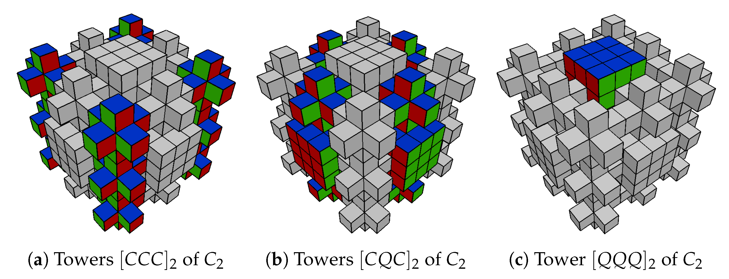
In order to find it, we can consider another decomposition of , relative to every direction, in the following pieces, which are polycubes in their own right. First, there are four pieces that are towers of three connected . We denote these by (in Figure 11a are highlighted the four towers in ). Second, there are four towers consisting of a , a and again a . We denote these by (in Figure 11b are highlighted the four towers in ). Finally, in the center, there is a tower of three ; we denote it by (in Figure 11c is highlighted the tower in ).
Contrary to what happens in , where the length of the segments can also be equal to , the length of all segments of is equal to a power of 3.
Lemma 1.
Segments in have a length for .
Proof.
Where a is in contact with another as in or with a as in , the only segments that enter into contact have a length of . The resulting segment in have a length of . The segments of the in that are not in contact with a form the only segments of length of . Since all segments of length less than in such a do not enter into contact with other segments (from other or ), with a straightforward inductive argument, it can be shown that all other segments, that all come from a , have length for . □
By we denote the number of segments of length in .
Proposition 1.
In , the number of segments of length is (for each direction):
Proof.
We use induction on n. For , the statement is obvious, because in , there is only one segment of length 3 in each direction.
Supposing that the proposition holds for , we proved it for n.
As shown in the proof of Lemma 1, a part of the segments of length comes from the and the . The number of those segments is equal to the number of segments of length in a , that is, . The remaining segments of length come from the and hence there are of those. Using the induction hypothesis, it now follows that in total we have:
□
Proposition 2.
In , the number of segments of length , for is (for each direction):
Proof.
As shown in the proof of Lemma 1, the segments of length , in each direction, come from the pieces contained in the towers that are denoted . The number of these segments is equal to the number of segments in that do not enter in contact with a segment from a in the same tower. In other words, for each , there are segments of length , that is:
Instead, the segments of length for come from the 20 copies of that are present in . Since all segments of length less than in such a do not enter into contact with other segments, for each direction and every , we have:
□
These results immediately prove the following theorem.
Theorem 2.
The level-n Menger sponge complement is formed in every direction of segments of length , and of segments of length for every .
Example 2.
The number of segments of a level-3 Menger sponge complement, in each direction, along with their lengths is given by the table (Table 3).
5. Concluding Remarks
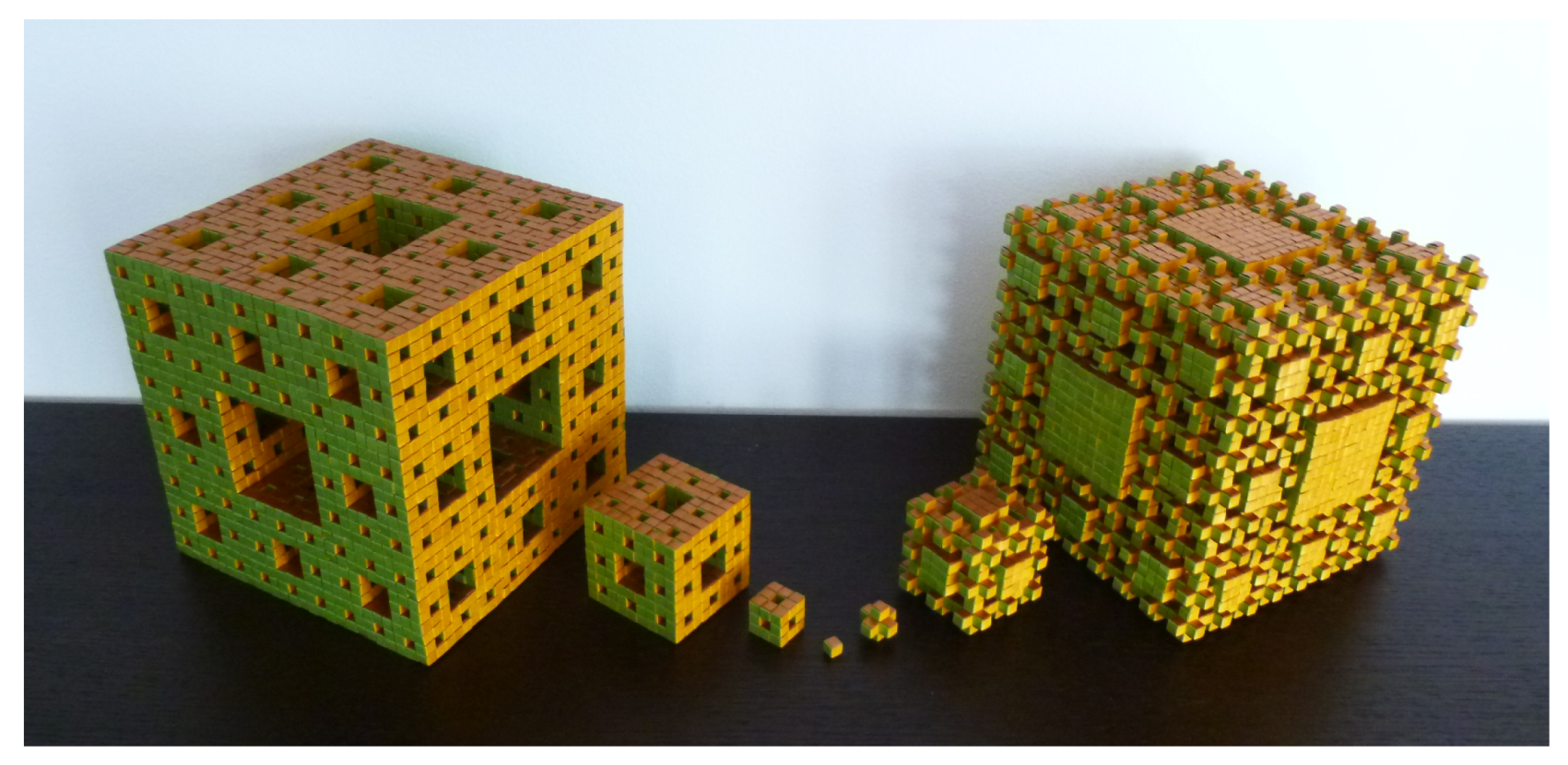
- With the PJS technique, the author constructed Menger sponges until the fourth level and complements of Menger sponges until level-3. A recent project led to the construction of the entire family of Menger sponges and their complements until level-3, using strips of Cordenon’s Stardream paper just 4 mm wide and of three different colors (Figure 12).The height of the sponge of level-3, and of its complement, is just cm. Note that working with smaller strips considerably increases the difficulty of assembling the cube.
- To realize the origami level-4 Menger sponge, the author used strips of paper 12 mm wide. At the time of writing, the construction of the complement was not planned. In any case, it would be preferable to make it using strips that are noticeably smaller in width. This would make the work more complicated but it would also make it easier to transport it and find a good place for it. For the fourth level sponge, about 21 km of paper strips were used; in fact, the edges are just over 1 m long and weigh about 25 kg. A model of this size is certainly fascinating to see, but it is also fascinating that it is decidedly impractical to expose and until now the sponge has not found a permanent home.
- The construction of a level above the fourth of a Menger sponge is very difficult because it would require a huge amount of paper and work. In fact, the PJS technique is not suitable for collaborative projects.
- Using the PJS technique, the author also created puzzles and dynamic origami models. The latest application concerns the creation of pixel art portraits.
- It is likely that the PJS technique, that was developed to realize polycubes in origami, can also be adapted for the construction of structures made by thin and malleable materials other than paper.
Funding
This research received no external funding.
Acknowledgments
The author would like to thank Willem A. de Graaf for his help in writing the paper, Alessandro Beber and Pooya Sareh for several helpful hints and Francesco Finarolli for the photo of the level-4 origami Menger sponge (Figure 2). Thanks also go to Jonathon Quinn, the developer of the app “Qubism 3D modeling”, with which all the graphics in this article were made. Finally, the author gratefully thanks the anonymous referees for the constructive comments and recommendations which have allowed to improve the quality of the exposition.
Conflicts of Interest
The authors declare no conflict of interest.
References
- Lang, R.J. Twists, Tilings, and Tessellations. Mathematical Methods for Geometric Origami; CRC Press: Boca Raton, FL, USA, 2018. [Google Scholar]
- DiLeonardo-Parker, B. Six Simple Twists: The Pleat Pattern Approach to Origami Tessellation Design, 2nd ed.; A K Peters; CRC Press: Boca Raton, FL, USA, 2021. [Google Scholar]
- Sareh, P. The least symmetric crystallographic derivative of the developable double corrugation surface: Computational design using underlying conic and cubic curves. Mater. Des. 2019, 183, 108128. [Google Scholar] [CrossRef]
- Sareh, P.; Chen, Y. Intrinsic non-flat-foldability of two-tile DDC surfaces composed of glide-reflected irregular quadrilaterals. Int. J. Mech. Sci. 2020, 185, 105881. [Google Scholar] [CrossRef]
- Nojima, T. Modelling of Folding Patterns in Flat Membranes and Cylinders by Origami. JSME Int. J. Ser. C Mech. Syst. Mach. Elem. Manuf. 2002, 45, 364–370. [Google Scholar] [CrossRef] [Green Version]
- Montroll, J. Origami Polyhedra Design; Taylor & Francis: Abingdon, UK, 2009. [Google Scholar]
- Hull, T. Project Origami: Activities for Exploring Mathematics; Taylor & Francis: Abingdon, UK, 2006. [Google Scholar]
- Ikegami, U. Fractal Crease Patterns. In Origami4. Fourth International Meeting of Origami Science, Mathematics, and Education; Lang, R.J., Ed.; A K Peters Ltd. (GB): Wellesley, MA, USA, 2009; pp. 31–40. [Google Scholar]
- Fuse, T. Unit Origami: Multidimensional Transformations; Japan Publications: Tokyo, Japan, 1990. [Google Scholar]
- Loper, B. Mind-Blowing Modular Origami: The Art of Polyhedral Paper Folding; Tuttle Publishing: Clarendon, VT, USA, 2016. [Google Scholar]
- Mosely, J. Crowdsourcing Origami Sculptures. In Origami6. Vol. 2. Technology, Art, Education; Miura, K., Kawasaki, T., Tachi, T., Uehara, R., Lang, R.J., Wang-Iverson, P., Eds.; American Mathematical Society: Providence, RI, USA, 2015; pp. 625–634. [Google Scholar]
- Cicalò, S. The PJS technique and construction of the first origami level-4 Menger sponge. In Origami7. Vol. 2. Mathematics; Lang, R.J., Bolitho, M., Zhoug, Y., Eds.; Tarquin: St. Albans, UK, 2018; pp. 653–668. [Google Scholar]
Figure 1.
A polycube.

Figure 2.
Level-4 origami Menger sponge.

Figure 3.
Assembly.

Figure 4.
Cartesian space.

Figure 5.
All segments in the three spatial directions. (a) x direction; (b) y direction; (c) z direction.
Figure 5.
All segments in the three spatial directions. (a) x direction; (b) y direction; (c) z direction.

Figure 6.
All modules in the three spatial directions.

Figure 7.
The construction of the polycube in Figure 1.
Figure 7.
The construction of the polycube in Figure 1.

Figure 8.
First three levels of the Menger sponge fractal.

Figure 9.
First three levels of the complement of the Menger sponge fractal.

Figure 10.
as a polycube composed of copies of and of .

Figure 11.
as a polycube composed by towers , and .

Figure 12.
Menger sponges and complements until third level.


Table 1.
Number of segments in the three spatial directions.
| x Direction | y Direction | z Direction | |||
|---|---|---|---|---|---|
| Length | Number | Length | Number | Length | Number |
| 1 | 8 | 1 | 3 | 1 | 4 |
| 2 | / | 2 | 1 | 2 | 2 |
| 3 | 1 | 3 | 2 | 3 | 1 |
Table 2.
The number of segments of a level-4 Menger sponge for each length, in each direction.
| Lenght | Number |
|---|---|
| 81 | 256 |
| 27 | 512 |
| 18 | 512 |
| 9 | 1536 |
| 6 | 3584 |
| 3 | 5632 |
| 2 | 19,968 |
| 1 | 24,064 |
Table 3.
The number of segments of a level-3 Menger sponge complement for each length, in each direction.
Table 3.
The number of segments of a level-3 Menger sponge complement for each length, in each direction.
| Lenght | Number |
|---|---|
| 27 | 217 |
| 9 | 256 |
| 3 | 640 |
| 1 | 1600 |
Publisher’s Note: MDPI stays neutral with regard to jurisdictional claims in published maps and institutional affiliations. |
© 2021 by the author. Licensee MDPI, Basel, Switzerland. This article is an open access article distributed under the terms and conditions of the Creative Commons Attribution (CC BY) license (https://creativecommons.org/licenses/by/4.0/).
Share and Cite
MDPI and ACS Style
Cicalò, S. The Construction of the Origami Level-n Menger Sponge Complement by the PJS Technique. Crystals 2021, 11, 468. https://doi.org/10.3390/cryst11050468
AMA Style
Cicalò S. The Construction of the Origami Level-n Menger Sponge Complement by the PJS Technique. Crystals. 2021; 11(5):468. https://doi.org/10.3390/cryst11050468
Chicago/Turabian StyleCicalò, Serena. 2021. "The Construction of the Origami Level-n Menger Sponge Complement by the PJS Technique" Crystals 11, no. 5: 468. https://doi.org/10.3390/cryst11050468
Note that from the first issue of 2016, this journal uses article numbers instead of page numbers. See further details here.