
You also want an ePaper? Increase the reach of your titles
YUMPU automatically turns print PDFs into web optimized ePapers that Google loves.
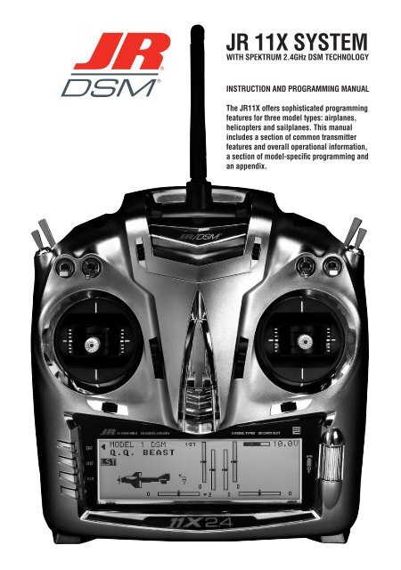
<strong>JR</strong> <strong>11X</strong> <strong>SYSTEM</strong><br />
WITH SPEKTRUM 2.4GHz DSM TECHNOLOGY<br />
INSTRUCTION AND PROGRAMMING MANUAL<br />
The <strong>JR</strong><strong>11X</strong> offers sophisticated programming<br />
features for three model types: airplanes,<br />
helicopters and sailplanes. This manual<br />
includes a section of common transmitter<br />
features and overall operational information,<br />
a section of model-specific programming and<br />
an appendix.
NOTICE<br />
All instructions, warranties and other collateral documents are subject to change at the sole discretion of Horizon Hobby, Inc.<br />
For up to date product literature, visit http://www.horizonhobby.com and click on the support tab for this product.<br />
Meaning of Special Language:<br />
The following terms are used throughout the product literature to indicate various levels of potential harm<br />
when operating this product:<br />
NOTICE: Procedures, which if not properly followed, create a possibility of physical property damage AND a<br />
little or no possibility of injury.<br />
CAUTION: Procedures, which if not properly followed, create the probability of physical property damage AND<br />
a possibility of serious injury.<br />
WARNING: Procedures, which if not properly followed, create the probability of property damage, collateral<br />
damage, and serious injury OR create a high probability of superficial injury.<br />
WARNING: Read the ENTIRE instruction manual to become familiar with the features of the product<br />
before operating. Failure to operate the product correctly can result in damage to the product,<br />
personal property and cause serious injury.<br />
This is a sophisticated hobby product and NOT a toy. It must be operated with caution and common sense and<br />
requires some basic mechanical ability. Failure to operate this Product in a safe and responsible manner could result<br />
in injury or damage to the product or other property. This product is not intended for use by children without direct<br />
adult supervision. Do not attempt disassemble, use with incompatible components or augment product in any way<br />
without the approval of Horizon Hobby, Inc. This manual contains instructions for safety, operation and maintenance.<br />
It is essential to read and follow all the instructions and warnings in the manual, prior to assembly, setup or use, in<br />
order to operate correctly and avoid damage or serious injury.<br />
TAbLE Of CONTENTS<br />
<strong>JR</strong> <strong>11X</strong> Transmitter and Receiver Specifications and features ......4<br />
<strong>Model</strong>Match .....................................................................................................4<br />
Advanced Digital Trims .....................................................................................4<br />
Compatible Receivers .......................................................................................4<br />
Charging ...........................................................................................................4<br />
The <strong>JR</strong> R921 .....................................................................................................5<br />
Binding .............................................................................................................6<br />
How to Bind ......................................................................................................6<br />
Failsafe Functions.............................................................................................6<br />
Range Testing ...................................................................................................6<br />
Receiver Power System Requirements .............................................................7<br />
Transmitter Identification (Mode 2) ..................................................................8<br />
Airplane Mode ..................................................................................................9<br />
Helicopter Mode ...............................................................................................9<br />
Sailplane Mode.................................................................................................9<br />
Initial <strong>Model</strong> Setup Guide ........................................................................10<br />
Trim Position Memory ....................................................................................10<br />
Quick Information Screen ...............................................................................10<br />
Quick Edit Mode .............................................................................................10<br />
System List ..................................................................................................10<br />
Function List ...................................................................................................10<br />
My List ............................................................................................................10<br />
<strong>JR</strong> <strong>11X</strong> <strong>SYSTEM</strong><br />
WITH SPEKTRUM 2.4GHz DSM TECHNOLOGY<br />
INSTRUCTION AND PROGRAMMING MANUAL<br />
Accessing the System List ..............................................................................11<br />
<strong>Model</strong> Select ...................................................................................................11<br />
Copy ...............................................................................................................11<br />
Erase ...............................................................................................................12<br />
Type Select .....................................................................................................12<br />
<strong>Model</strong> Name ...................................................................................................12<br />
Flight Mode Name ..........................................................................................12<br />
Warning ..........................................................................................................13<br />
TX Settings .....................................................................................................13<br />
All Servos Hold...............................................................................................13<br />
Trainer .............................................................................................................13<br />
<strong>11X</strong> Used as Master .......................................................................................14<br />
<strong>11X</strong> Used as Slave ..........................................................................................14<br />
Stick Alert .......................................................................................................14<br />
Devise Select ..................................................................................................14<br />
Flight Modes (Airplane) ..................................................................................15<br />
Switch Assignments .......................................................................................15<br />
Active/Inhibit Channels ..................................................................................15<br />
Wing Type .......................................................................................................16<br />
V-Tail ..............................................................................................................16<br />
Dual Control Functions ..................................................................................16<br />
To Program a Wing Type ................................................................................16<br />
TAbLE Of CONTENTS<br />
Dual Channels ................................................................................................16<br />
Twin Engine ....................................................................................................17<br />
Flight Modes (Helicopter) ...............................................................................17<br />
Activating Extra Flight Modes 3 and 4 ............................................................17<br />
Switch Assignments .......................................................................................17<br />
Assigning/Activating Governor and Gyro Functions ......................................17<br />
Deactivating Channels ....................................................................................17<br />
Swashplate Type .............................................................................................18<br />
Flight Modes (Sailplane) ................................................................................18<br />
Activating and Assigning Primary Flight Modes ............................................18<br />
Activating and Assigning Additional Flight Modes ........................................18<br />
Motor Function ...............................................................................................19<br />
Flap and Aux Functions ..................................................................................19<br />
Activating/Inhibiting Channels .......................................................................19<br />
Wing Type .......................................................................................................19<br />
Flap Stick Direction ........................................................................................19<br />
function List ...............................................................................................19<br />
Dual Rate and Exponential ..............................................................................19<br />
Auto Function .................................................................................................20<br />
Travel Adjust ...................................................................................................20<br />
Limit Adjust ....................................................................................................20<br />
Sub-Trim .........................................................................................................20<br />
Servo Reversing .............................................................................................20<br />
Servo Speed ...................................................................................................20<br />
Throttle Curves (Airplane) ..............................................................................21<br />
Throttle Curves (Helicopter) ...........................................................................21<br />
Pitch Curve .....................................................................................................22<br />
Point Names/Numbers ...................................................................................22<br />
Current Point Settting .....................................................................................22<br />
Vertical Line ....................................................................................................22<br />
Graph ..............................................................................................................22<br />
Points You Can Add and Adjust .....................................................................22<br />
Exponential .....................................................................................................22<br />
Pitch Channel Position ...................................................................................22<br />
Throttle Channel Position ...............................................................................22<br />
Switch Select ..................................................................................................23<br />
Flap System ....................................................................................................23<br />
Flap .................................................................................................................23<br />
ELEV - Elevator Compensation .......................................................................23<br />
AILE - Aileron Compensation .........................................................................23<br />
Flight Modes ..................................................................................................23<br />
Delay ...............................................................................................................24<br />
Snap Roll ........................................................................................................24<br />
Differential ......................................................................................................24<br />
Aileron to Rudder............................................................................................24<br />
Aileron-to-Flap Mix ........................................................................................25<br />
Elevator to Flap ...............................................................................................25<br />
Rudder to Aileron/Elevator Mix ......................................................................25<br />
Trim (Mechanical Trim Lever) .........................................................................25<br />
Hovering Throttle ............................................................................................26<br />
Pitch Curve .....................................................................................................26<br />
Exponential .....................................................................................................26<br />
Hovering Pitch ................................................................................................26<br />
Tail Curve - (Use Only with Non-Heading Hold Gyros) ..................................26<br />
Throttle Hold ...................................................................................................27<br />
Stick Auto .......................................................................................................27<br />
Hold Delay ......................................................................................................27<br />
Gyro Sensor ....................................................................................................27<br />
Governor .........................................................................................................28<br />
Swash Mix ...................................................................................................28<br />
Aileron, Elevator and Pitch Authority ..............................................................28<br />
Aileron to Elevator/Elevator to Aileron Mix .....................................................28<br />
3D Electronic Cyclic Ring (E-Ring) ................................................................28<br />
Exponential Function ......................................................................................28<br />
Trim System ....................................................................................................28<br />
L.S.T. Trim (Limited Standard Trim) ................................................................29<br />
Slide Camber ..................................................................................................29<br />
Motor System .................................................................................................29<br />
Camber Preset ................................................................................................29<br />
Landing Mode ................................................................................................30<br />
Differential ......................................................................................................30<br />
Flaperon Mix ..................................................................................................30<br />
Aileron-to-Rudder Mix ...................................................................................31<br />
Snap-to-Flap Mix ...........................................................................................31<br />
Rudder-to-Spoiler Mix....................................................................................31<br />
Introduction to Mixers ..............................................................................31<br />
Functions of the Standard Programmable Mixer ............................................32<br />
Master Channel-(STD. PROG MIXER) ...........................................................32<br />
Slave Channel-(STD. PROG MIXER) ..............................................................32<br />
Switch Position ...............................................................................................32<br />
Offset ..............................................................................................................32<br />
Mix Values ......................................................................................................32<br />
CLR Button-(STD. PROG MIXER) Slave Channel ..........................................33<br />
To Inhibit a Mix ...............................................................................................33<br />
Multi-Point Programmable Mixer ..................................................................33<br />
Point Names/Numbers ...................................................................................33<br />
Current Point Setting ......................................................................................33<br />
Vertical Line ....................................................................................................33<br />
Graph ..............................................................................................................33<br />
Points You Can Add and Adjust .....................................................................33<br />
Exponential .....................................................................................................33<br />
Slave Channel Position ..................................................................................34<br />
Master Channel Position ................................................................................34<br />
Mix to Thottle .................................................................................................34<br />
Selecting the Desired Flight Modes for Cyclic-to-Throttle Mixing .................34<br />
F-Mode Delay .................................................................................................34<br />
Gyro Gain System [Sensor] ............................................................................34<br />
Gyro Connection ............................................................................................34<br />
Gyro Sensor [Gain] .........................................................................................34<br />
Trim System ....................................................................................................35<br />
L.S.T. Trim (Limited Standard Trim) ................................................................35<br />
Throttle Hold ...................................................................................................35<br />
Throttle Trim ...................................................................................................35<br />
Balance ...........................................................................................................36<br />
Stick Position Switch ......................................................................................36<br />
Timer ..............................................................................................................36<br />
Mix Monitor ....................................................................................................37<br />
Monitor ...........................................................................................................37<br />
Frequently Asked Questions on Spektrum 2.4GHz .........................................38<br />
General Information ........................................................................................39<br />
Warranty and Repair Policy ....................................................................39<br />
3 Year Limited Warranty .................................................................................39<br />
Damage Limits................................................................................................39<br />
Warranty Services .....................................................................................41<br />
Questions, Assistance and Repairs.................................................................40<br />
Inspection or Repairs ......................................................................................40<br />
Warranty Inspection and Repairs ....................................................................41<br />
Non-warranty Repairs .....................................................................................41<br />
Appendix ......................................................................................................42<br />
Flight Log <strong>JR</strong>PA - Optional for Jr <strong>JR</strong> R921 Receiver ......................................42<br />
Advanced Range Testing .................................................................................43<br />
Control Stick Tension Adjustment ..................................................................43<br />
2 <strong>JR</strong> <strong>11X</strong> • RADIO INSTRUCTION MANUAL <strong>JR</strong> <strong>11X</strong> • RADIO INSTRUCTION MANUAL<br />
3
<strong>JR</strong> <strong>11X</strong> TRANSMITTER AND<br />
RECEIvER SPECIfICATIONS<br />
AND fEATURES<br />
With Spektrum’s 2.4GHz DSM technology, the <strong>JR</strong> <strong>11X</strong> offers a hassle-free,<br />
interference-free superior RF link for your airplane, helicopter or sailplane.<br />
The same technology also significantly reduces latency so you have a more<br />
responsive, precise connection to your aircraft. All of this means you can fly with<br />
confidence and safety when you fly with the <strong>11X</strong>.<br />
<strong>SYSTEM</strong> SPECIfICATIONS<br />
<strong>JR</strong> <strong>11X</strong> Transmitter features:<br />
• Backlit screen<br />
• Digital 3 + 1 trims (3 digital + 1 analog [throttle] trim)<br />
• Dual ball bearings<br />
• Fully integrated 2.4GHz Spektrum technology<br />
• Sophisticated programming for three model types: Airplane,<br />
Helicopter, Sailplane<br />
• Rolling Selector input<br />
• Flight Mode naming<br />
• 30-model memory<br />
• Patented DuaLink® Technology<br />
• <strong>Model</strong>Match<br />
• ServoSync<br />
• Advanced Digital Trims<br />
Transmitter Specifications:<br />
• <strong>Model</strong> Number: (<strong>11X</strong> 2.4, <strong>JR</strong>P1100)<br />
• Number of Channels: 11<br />
• Modulation Type: Direct Sequence Spread Spectrum<br />
DSM2/ DSM1 protocol<br />
• Band: 2.400–2.483GHz<br />
• Transmitter Current: 180mA/DSM2; 280mA/DSM1<br />
• Resolution: 2048<br />
Receiver features:<br />
• Instant QuickConnect (with brownout detection) should a<br />
power interruption occur<br />
• Flight Log compatible<br />
• 9 channels<br />
• 2 internal receivers<br />
• 1 remote receiver, a 2nd remote receiver is optional<br />
(<strong>JR</strong>PRR121)<br />
• Patented MultiLink technology<br />
• Two Types of Failsafe: SmartSafe and Preset Failsafe<br />
Receiver Specifications:<br />
• Number of Channels: 9<br />
• Modulation: DSM2<br />
• Band: 2.400–2.4835GHz<br />
• Dimensions (WxLxH): 1.23 x 1.94 x .56 in<br />
• Weight: Main .6 oz (15 g); Remote .2 oz (3 g) each<br />
• Current: 70mA<br />
• Voltage Range: 3.5 to 10V<br />
• Resolution: 2048<br />
MODELMATCH<br />
Patent pending <strong>Model</strong>Match technology prevents the operation of your model,<br />
if you select the wrong model memory. During binding the receiver learns the<br />
model’s memory (1 through 30) the transmitter is currently programmed to.<br />
Later, if you select the incorrect model memory in the transmitter and turn the<br />
receiver on, the model won’t operate. This prevents a possible crash. Change the<br />
programming to the correct model memory, and you can fly.<br />
ADvANCED DIGITAL TRIMS<br />
The <strong>11X</strong> features Advanced digital trims. On the Normal display screen, if you<br />
move a trim lever, the screen automatically displays the graphic position for the<br />
trim being adjusted. The <strong>11X</strong> Aileron, Elevator and Rudder trim levers and the<br />
right and left rear levers feature an audible center trim beep. This helps when<br />
determining the trim lever’s center position during flight. In addition, the frequency<br />
of each trim step changes from full right/up to full left/down on the three front<br />
digital trims. This allows you to be aware of the general trim position audibly<br />
without looking at the transmitter.<br />
By using the Trim System Function located in the System List, you can adjust the<br />
amount of travel per each trim step as needed for your specific application. When<br />
you turn the <strong>11X</strong> off, the transmitter stores the trim values and recalls them when<br />
turned back on.<br />
COMPATIbLE RECEIvERS<br />
Note: The <strong>11X</strong> is compatible with all current <strong>JR</strong> and Spektrum DSM aircraft<br />
receivers including:<br />
• AR500 5-channel Parkflyer Receiver<br />
• AR6000 6-channel Parkflyer Receiver<br />
• AR6100 6-channel 3.5-gram Parkflyer Receiver<br />
• AR6100e 6-channel 3.5-gram End Pin Parkflyer Receiver<br />
• AR6110/AR6110E 6-channel Parkflyer Receiver/End Pin<br />
• AR6200 6-channel Full Range Receiver<br />
• AR6250 6-channel Carbon Fuse Full Range Receiver<br />
• AR6300 6-channel 2-gram Nanolite Slow and Micro Flyer Receiver<br />
• AR6400/L 6-channel Receiver<br />
• AR7000 7-channel Full Range Receiver<br />
• AR7600 7-channel High-Speed Receiver<br />
• AR7100/AR7100R 7-channel Heli Receiver/with RevLimit<br />
• AR9000 9-channel Receiver<br />
• AR9100 9-channel PowerSafe Receiver<br />
• AR9200 9-channel PowerSafe Evolution Receiver<br />
• AR9300 9-channel Carbon Fuse Receiver<br />
• AR12000 12-channel Receiver<br />
• AR12100 12-channel PowerSafe Receiver<br />
• R922 9-channel PowerSafe Receiver<br />
• R1221 12-channel Receiver<br />
• R1222 12-channel PowerSafe Receiver<br />
CAUTION: When using the <strong>11X</strong> with slow and park flyer receivers (the<br />
AR6000, AR6100, AR6100e, AR6110, AR6110E, AR6300, AR6400 and<br />
AR7600 when the remote receiver is not connected), you should only fly these<br />
receivers in park flyer-type aircraft (small electric airplanes or mini and micro<br />
helicopters). Flying receivers designed for park flyers in larger aircraft could<br />
cause a loss of control resulting in damage to property and/or injury.<br />
CHARGING<br />
Do’s and Don’ts<br />
• Charge transmitter and receiver battery before flying.<br />
• Check receiver battery charge between each flight using a tester with built-in<br />
load.<br />
• Only use charger on <strong>JR</strong> equipment. Charge plug polarity may be different.<br />
Equipment damage can result.<br />
• Do not use other manufacturer’s after-market accessories that plug into<br />
transmitter charging jack. If you doubt polarity compatibility, seek expert<br />
advice to avoid possible damage.<br />
• The center pin on all <strong>JR</strong> transmitters is negative. Therefore, all <strong>JR</strong> chargers<br />
have a negative center pin, not positive.<br />
• Beware of improper connections based on color-coded wire leads—they<br />
may not apply.<br />
• ALWAYS connect the center pin of y our <strong>JR</strong> transmitter to the negative pole<br />
for correct polarity.<br />
Instructions<br />
1. Plug the charger into the <strong>11X</strong> battery port on the right side of the radio.<br />
2. Plug the charger power supply into the wall outlet.<br />
CAUTION: Not following proper sequence of numbers 1 and 2 can cause a<br />
static short, which could damage the battery circuitry.<br />
3. For initial charge and any charging of fully discharged battery, charge time<br />
is 10–12 hours. Charge time decreases if battery is not fully discharged.<br />
4. Monitor the temperature of battery during charging.<br />
5. After charging, check the voltage of the battery pack by turning system on.<br />
Voltage should be just over 11 volts (11.4 approximately but will vary).<br />
6. During first use, battery voltage may drop below 9.6 volts. Charge the<br />
battery again to just over 11 volts. Do not overcharge.<br />
Notes<br />
• The <strong>11X</strong> battery contains a heat detector. If it senses excessive heat, it shuts<br />
off the charger and shows an error on the charger LED.<br />
• The battery voltage does not affect the output of the system as the output is<br />
regulated internally.<br />
• The <strong>11X</strong> charger is not a peak detect charger. If using a fast charger for<br />
the transmitter battery, do not exceed 1.5 amps (1500mA) charge rate or<br />
damage to transmitter or battery can occur.<br />
• The <strong>11X</strong> charger output is DC 11.6V, with 110mA as the average charge rate.<br />
• If using a peak detection charger, make sure battery is fully charged. NiMH<br />
batteries tend to repeatedly false peak with peak detection fast chargers. Use<br />
a charger that displays the total charge current. Note the number of mAh put<br />
into a discharged pack to verify it charges to capacity.<br />
Safety Precautions and Warnings<br />
Failure to exercise caution while using this product and comply with the<br />
following warnings could result in product malfunction, electrical issues,<br />
excessive heat, FIRE, and ultimately injury and property damage.<br />
• If the transmitter voltage drops below 9.0 volts or the battery alarm goes off<br />
during flight, land immediately and recharge.<br />
• Read all safety precautions and literature prior to use of this product.<br />
• Never leave battery and charger unattended during use.<br />
• Never allow minors to charge battery packs without adult supervision.<br />
• Never attempt to charge dead or damaged batteries.<br />
• Never charge a battery if the cable has been pinched or shorted.<br />
• Never allow batteries or charger to come into contact with moisture at any<br />
time.<br />
• Never charge batteries in extremely hot or cold places (recommended<br />
between 50–80 drees Fahrenheit) or place in direct sunlight.<br />
• Always use only compatible NiMH rechargeable batteries. This charger<br />
cannot charge batteries such as “heavy duty,” “alkaline battery,” or<br />
“mercury battery.”<br />
• Always properly connect charger and battery.<br />
• Always disconnect the battery and hcarger after charging, and let them cool<br />
between charges.<br />
• Always inspect the battery before charging.<br />
• Always terminate all processes and contact Horizon Hobby if the product<br />
malfunctions.<br />
• Always monitor battery temperature while charging.<br />
• End charging process if the charger or battery comes hot to the touch or<br />
starts to change form during the charge process.<br />
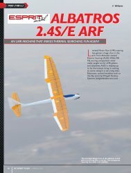
Charger Pigtail for Transmitter<br />
BLACK TO POSITIVE<br />
BLACK W/WHITE STRIPE TO NEGATIVE<br />
Transmitter Charge Jack Polarity<br />
WARNING: Charge only rechargeable batteries. Non-rechargeable<br />
batteries may burst causing injury to persons and/or damage to property.<br />
THe <strong>JR</strong> R921 ReCeIVeR<br />
The <strong>JR</strong> R921 incorporates two internal receivers and one remote receiver with<br />
an optional second remote receiver. You must plug 1 remote receiver into one of<br />
the remote receiver ports for the system to operate and a second remote receiver<br />
(optional) into the remaining remote antenna port.<br />
Installing the receivers in different locations throughout the aircraft exposes<br />
each receiver to its own RF environment. This greatly improves the ability of<br />
the receivers to see the signal in all conditions. This gives a solid RF link, even<br />
in aircraft that have substantial conductive materials (e.g., turbine engines with<br />
metal tail pipes, carbon fiber, tuned pipes, etc.) that can weaken the signal.<br />
Installing the R921<br />
Install the main receiver using the same method of a conventional receiver in<br />
your aircraft. Typically, wrap the main receiver in protective foam and fasten it in<br />
place using rubber bands or hook and loop straps. Alternately in electric models<br />
or in jets (low vibration),you can use thick double-sided foam tape to fasten the<br />
main receiver in place.<br />
Using double-sided foam tape (servo tape), mount the remote receiver(s)<br />
keeping it at least 2 inches away from the primary receiver. Ideally, you should<br />
position the antennas perpendicular to each other. 6-, 9-, 12-, 24-, and 36-inch<br />
leads are available. A standard installation includes the main receiver mounted<br />
conventionally in the fuselage and the remote antennas in the nose (jets) in<br />
the top turtle deck and even in the tail. The optimum location, especially for<br />
sophisticated aircraft, is as far away from any conductive materials as practical.<br />
In helicopters, the servo tray generally has enough room to achieve the<br />
necessary separation. When needed you can make a mount using clear plastic to<br />
position the remote receiver.<br />
Other important installation tips:<br />
1. Mount the servos using rubber grommets and brass eyelets to isolate them<br />
from vibration. Do not over-tighten the mounting screws; this will negate<br />
the vibration absorption effect of the rubber grommets. When mounting,<br />
push the brass eyelets from the bottom up in the rubber grommets. By<br />
tightening the servo screw securely, you provide the proper security and<br />
vibration isolation for your servo.<br />
2. The servo arms must be able to move freely over their entire range of travel.<br />
Make sure the control linkages do not bind or impede the movement of any<br />
of the servos.<br />
3. Mount all switches away from the engine exhaust and away from any high<br />
vibration areas. Make sure the switch operates freely and over its full travel.<br />
4 <strong>JR</strong> <strong>11X</strong> • RADIO INSTRUCTION MANUAL <strong>JR</strong> <strong>11X</strong> • RADIO INSTRUCTION MANUAL<br />
5<br />
-<br />
+
INDING<br />
Binding is necessary to program the receiver to the transmitter so the receiver<br />
only recognizes that specific transmitter, ignoring signals from any other sources.<br />
If the receiver is not bound to the transmitter, the system will not operate. During<br />
binding, the servo’s failsafe positions are stored.<br />
The following sequence describes the binding procedure for the <strong>JR</strong> R921. All <strong>JR</strong><br />
and Spektrum DSM aircraft receivers are bound in the same way.<br />
HOW TO bIND<br />
Note: To bind an aircraft with an electronic speed controller that powers the<br />
receiver through the throttle channel (BEC), insert the bind plug into the bind port<br />
and proceed to Step #2.<br />
1. With the system hooked up as shown, insert the bind plug in the charge plug<br />
receptacle. The switch must be a 3-wire type switch (<strong>JR</strong>PA001 or <strong>JR</strong>PA004)<br />
to enter bind mode through the switch. Plug the switch into the bind port<br />
R921<br />
of the receiver. If a 3-wire switch is not available, install the male bind plug<br />
directly into the receiver bind receptacle and power the receiver through any<br />
other open port to enter bind mode.<br />
2. Power on the receiver. The LEDs on all receivers should be flashing,<br />
indicating the receiver is ready to bind.<br />
3. Establish the desired failsafe stick positions: normally low throttle and flight<br />
controls neutral.<br />
4. Press and hold the bind button on the back of the transmitter while turning<br />
on the power switch. The bind lights on the front and rear of the transmitter<br />
should flash and within a few seconds the system should connect. The LEDs<br />
on the receivers should go solid, indicating the system has connected.<br />
5. Remove the bind plug from the receiver or switch harness and store in a<br />
convenient place.<br />
6. After programming your model, rebind the system so the true low throttle<br />
and neutral control surface positions are programmed.<br />
7. When the transmitter is turned on and operating with the system, the amber<br />
light on the rear of the transmitter will be on solid. The blue light on the<br />
top front of the transmitter will also be on solid indicating the system is<br />
outputting signal and operating.<br />
fAILSAfE fUNCTIONS<br />
The <strong>JR</strong> R921 receiver features two types of failsafe programming: SmartSafe and<br />
Preset Failsafe.<br />
SmartSafe<br />
SmartSafe is automatically selected during the standard binding procedure and is<br />
ideal for electric aircraft as well as most gas- and glow-powered aircraft.<br />
How SmartSafe Works<br />
• When the Receiver is Powered On without a Transmitter Signal<br />
If you turn on the R291 before you turn on the transmitter, SmartSafe<br />
prevents the throttle from functioning and drives all other channels to their<br />
preset positions.<br />
• When there is a Loss of Signal in flight<br />
If the receiver loses the transmitter’s signal in flight, or any other time after<br />
a successful connection has been made, SmartSafe sets the throttle to the<br />
position it was in during the binding process. All other channels hold the<br />
positions they were in at signal loss.<br />
How to Program the Receiver for SmartSafe<br />
Simply move the throttle to a desired in-flight failsafe position (typically this is<br />
all the way back) and bind the receiver to the transmitter. Leave the bind plug in<br />
the receiver during the entire binding process. Remove the bind plug only after a<br />
connection has been made and the controls are functioning normally.<br />
Preset failsafe<br />
Preset Failsafe allows you to set the specific control positions for all channels<br />
to go to should you encounter signal loss in flight or at any other time after a<br />
successful connection has been made. Preset Failsafe is typically used to prevent<br />
“fly aways” in high-performance models by deploying spoilers in sailplanes or<br />
putting gas- and glow-powered models into a slight turn at reduced throttle.<br />
How to Program Preset failsafe Settings<br />
Insert the bind plug and power on the receiver. When the receiver’s LED lights<br />
begin to blink indicating it is in bind mode, remove the bind plug before binding<br />
the transmitter to the receiver. The LED lights on the receiver continue to blink.<br />
Move your transmitter’s control sticks and switches to the desired Preset Failsafe<br />
positions then turn it on in bind mode. The system should connect in less than<br />
15 seconds.<br />
RANGE TESTING<br />
The Standard Range Testing procedure is recommended for most sport aircraft.<br />
Range Testing<br />
1. With the model resting on the ground, stand 30 paces (approx. 90 feet) away<br />
from the model.<br />
2 Face the model with the transmitter in your normal flying position and<br />
depress and hold the bind button on the back of the transmitter. This causes<br />
reduced power output from the transmitter.<br />
3 You should have total control of the model with the button depressed at 30<br />
paces (90 feet).<br />
4 If control issues exist, call Product Support at 1-877-504-0233 for further<br />
assistance.<br />
30 paces (90 feet/27 meters)<br />
RECEIvER POWER <strong>SYSTEM</strong><br />
ReQUIReMeNTS<br />
The onboard power system must provide adequate power without interruption<br />
to the receiver even when the servos are at maximum flight loads. Inadequate<br />
power systems that do not provide the necessary minimum voltage to the receiver<br />
during flight loads are the number one cause of in-flight failures. Some power<br />
system components that affect the ability to properly deliver adequate power<br />
include: the selected receiver battery pack (number of cells, capacity, cell type,<br />
state of charge), switch harness, battery leads, and if used, the regulator and<br />
power bus.<br />
Recommended Power System Guidelines<br />
1. When setting up large or complex aircraft with multiple high-torque servos,<br />
you should use a current and voltmeter (HAN172). Plug the voltmeter in an<br />
open channel port in the receiver and, with the system on, load the control<br />
surfaces (apply pressure with your hand). Monitor the voltage at the receiver.<br />
The voltage should remain above 4.8 volts even when all servos are heavily<br />
loaded. The optional Flight Log has a built-in voltmeter and can be used.<br />
2. With the current meter in line with the receiver battery lead, load the<br />
control surfaces while monitoring the current. The maximum continuous<br />
recommended current for a single heavy-duty servo/battery lead is three<br />
amps. Short duration current spikes of up to five amps are acceptable.<br />
If your system draws more than these currents, you should use multiple<br />
packs with multiple switches and multiple leads plugged into the receiver.<br />
While a <strong>JR</strong> receiver’s minimum operational voltage is 3.5 volts, you should<br />
test the system to a minimum acceptable voltage of 4.8 volts during ground<br />
testing. This provides headroom to compensate for battery discharging or if<br />
the actual flight loads are greater than the ground test loads.<br />
Note: <strong>JR</strong>’s amplified Y-harness (<strong>JR</strong>PA133) is for use with Z-PCM only. <strong>JR</strong>’s<br />
non- amplified Y-harness (<strong>JR</strong>PA135) should be used with PPM, SPCM or<br />
DSM/DSM2 systems.<br />
3. If using a regulator, perform the above tests for an extended period of 5<br />
minutes. When current passes through a regulator, heat is generated. This<br />
causes the regulator to increase resistance, causing even more heat to build<br />
up (thermal runaway). While a regulator may provide adequate power for a<br />
short duration, you should test its ability over time. The regulator may not be<br />
able to maintain voltage at significant power levels.<br />
4. For really large aircraft or complex models (for example 35% and larger or<br />
jets), multiple battery packs with multiple switch harnesses are necessary<br />
or, in many cases, one of the commercially available power boxes/busses is<br />
recommended. No matter what power system you choose, always carry out<br />
test #1 above. Make sure the receiver is constantly provided with 4.8 volts or<br />
more under all conditions.<br />
6 <strong>JR</strong> <strong>11X</strong> • RADIO INSTRUCTION MANUAL <strong>JR</strong> <strong>11X</strong> • RADIO INSTRUCTION MANUAL<br />
7
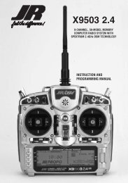
TRANSMITTeR IDeNTIFICATION (MODe 2)<br />
Antenna<br />
Gear Switch<br />
flight Mode Switch<br />
Left Trimmer/<br />
Trainer Switch<br />
flap Switch<br />
Elevator D/R<br />
Throttle/Rudder Stick<br />
Throttle Trim<br />
Rudder Trim<br />
Programming buttons<br />
Handle<br />
Mix Switch<br />
Right Slider<br />
Trainer Port<br />
Mix/Hold Switch<br />
Rudder D/R Switch<br />
Right Trimmer/<br />
Trainer Switch<br />
Aileron D/R<br />
Auxillary 2<br />
Aileron/elevator Stick<br />
Elevator Trim<br />
Aileron Trim<br />
Power Switch<br />
Rolling Selector<br />
LCD Screen<br />
Gear Switch<br />
Left Slider<br />
Rf Light<br />
Bind/Range Check Button<br />
battery Door<br />
WARNING: ENSURE fUTURE ANTENNA SAfETY<br />
Do not attempt to use the antenna to bear any weight, pick up the transmitter by the antenna or alter the antenna in any way. If the<br />
transmitter antenna or related components become damaged the output strength can be severely impeded which will likely lead to a crash,<br />
injury, and property damage.<br />
AIRPLANE - ACRO MODE<br />
The ACRO mode is for powered fixed-wing aircraft. It contains advanced features<br />
designed to assist the pilot in realizing the full potential of the aircraft. These<br />
features include:<br />
• Up to 3 flight modes<br />
• Switch and lever assignability<br />
• Triple Rates and Exponentials for Aileron, Elevator and Rudder that can be<br />
combined or assigned to flight modes<br />
• 4 programmable Wing Types (Normal, Flaperon, Delta, 4-aileron)<br />
• Differential with two values per channel (Aileron, Dual Rudder, Dual Flap)<br />
• V-Tail mixing<br />
• Dual Channels for All Primary Flight Controls and Flaps<br />
• Dual Throttles (With Independent Trims and Throttle Curves)<br />
• Adjustable Trim Rates (10–100 Trim Steps)<br />
• L.S.T. trim—trim can be programmed to affect endpoints or center point<br />
only<br />
• Elevator-To-Flap mixing<br />
• Aileron-To-Flap mixing<br />
HELICOPTER MODE<br />
The <strong>11X</strong> Heli Mode programming includes 6 swashplate types making it<br />
compatible with virtually every type of model helicopter. Some of the <strong>11X</strong>’s<br />
sophisticated Heli programming features include:<br />
• Switch Assignability for channels and functions<br />
• Up to six fully programmable Flight Modes<br />
• Flight Mode Naming allows custom naming of each flight mode.<br />
• Warning system allows custom programming of alarms for various switch<br />
and stick positions<br />
• Programmable Servo Speed<br />
• Triple Rates/Exponentials (up to 4 Rates/EXPOs for Aileron, Elevator and<br />
Rudder in flight modes)<br />
• 6 Swashplate Types (normal, 2 servo 180, 3 servo 120, 3 servo 140, 3 servo<br />
90, 4 servo 90)<br />
• Electronic 3D Cyclic Ring prevents overdriving the cyclic servos with<br />
SAILPLANE MODE<br />
The <strong>11X</strong> GLID programming is optimized for multi-function sailplanes and offers<br />
the highest level of versatility and sophistication. The system has many features<br />
including:<br />
• Switch Assignability for channels and functions<br />
• Up to 5 fully programmable Flight Modes<br />
• Flight Mode Naming allows custom naming of each flight mode<br />
• Dual control functions for elevator, rudder, flap and spoilers<br />
• V-tail mixing<br />
• Stick Position switches allow mixing functions to be turned on/off via a stick<br />
position<br />
• Fully programmable motor function<br />
• Camber programming for each flight mode<br />
• Balance mixing allows precise mixing of slave channel to master at multiple<br />
points<br />
• Throttle hold—can be assigned as a kill switch<br />
• Aileron-To-Rudder mixing<br />
• Throttle Curves (2)<br />
• Flap System (With Elevator and Aileron Trim, Auto Land, Elevator/Flap<br />
Delay)<br />
• Gyro System (In-Flight Gain Selection of up to 3 Gains for up to 2 Gyros)<br />
• Servo Speed (Independent in Both Directions – Eliminates Door<br />
Sequencers)<br />
• 6 Programmable Mixes (Includes 3 Multi-Point Mixes)<br />
• Programmable Trainer System (Selectable Channels for Student Control)<br />
• Timers- up to four (Stopwatch, Countdown, Integrated)<br />
• Servo Monitor (Automatically Renames Channels According to<br />
Assignments)<br />
• Pitch Curve Mixing for variable pitch props<br />
combined aileron and elevator commands<br />
• Adjustable Trim Rates (10 – 100 trim steps)<br />
• Built-In Cyclic-to-Throttle Mixing for Aileron, Elevator, and Rudder<br />
• Governor Mix<br />
• Throttle Curves (up to 5) with up to 7 programmable points<br />
• Pitch Curves (up to 6) with up to 7 programmable points<br />
• Gyro System (In Flight mode Gain Selection of up to 6 gains)<br />
• 6 Programmable Mixes (includes 3 multi-point and 3 standard mixes)<br />
• Programmable trainer system (selectable channels for Student Control)<br />
• 3 programmable timers that can be triggered w/ the throttle position or<br />
programmable switches<br />
• Servo Monitor (automatically renames channels according to assignments)<br />
• Mix Monitor displays all active mixes<br />
• Warning system allows custom programming of alarms for various switch<br />
and stick positions<br />
• Programmable servo speed<br />
• Triple Rates/Exponentials (up to 4 Rates/EXPOs for Aileron, Elevator and<br />
Rudder in flight modes)<br />
• Adjustable Trim Rates (10–100 Trim Steps)<br />
• 6 Programmable Mixes (includes 3 Multi-Point and 3 Standard mixes)<br />
• Programmable Trainer system (selectable channels for student control)<br />
• 3 Programmable Timers that can be triggered with the throttle position or<br />
programmable switches<br />
• Servo Monitor (automatically renames channels according to assignments)<br />
• Mix Monitor displays all active mixes<br />
8 <strong>JR</strong> <strong>11X</strong> • RADIO INSTRUCTION MANUAL <strong>JR</strong> <strong>11X</strong> • RADIO INSTRUCTION MANUAL<br />
9
INITIAL MODEL SETUP GUIDE<br />
The Initial <strong>Model</strong> Setup Guide function shows some basic functions to set up a<br />
new model when a model is erased or a new model selected. When setting up a<br />
new model or after erasing a model, the new model setup guide opens with the<br />
Type Select function.<br />
Select the Type of model desired; then the <strong>Model</strong> Name function appears. Enter<br />
the <strong>Model</strong> Name as desired. Select OK when the <strong>Model</strong> Name is set. Next the<br />
Wing Type menu appears. Select the desired Wing Type setting for your model.<br />
If the Wing Type setting is Delta the Initial <strong>Model</strong> Setup Guide will now exit.<br />
If the Wing Type setting selected is Normal, the Dual Aileron function appears;<br />
select a second aileron channel if desired. The V-Tail setting then appears. Select<br />
INH or ACT as necessary for your model. The Initial <strong>Model</strong> Setup Guide will now<br />
exit, and you can adjust any settings as desired.<br />
Select the Type of model desired. After the model type has been selected, the<br />
<strong>Model</strong> Name function will then appear. Enter the <strong>Model</strong> Name as desired. See<br />
page 12 for more information on setting the <strong>Model</strong> Name. Press OK when the<br />
<strong>Model</strong> Name is set as desired. Next the Swash Type menu appears. Select the<br />
Swash Type setting for your model. Next the Gyro Channel setting appears.<br />
Select the channel for the gyro gain you will use d for the helicopter. Select INH if<br />
you do not wish to use the Gyro function. The Initial <strong>Model</strong> Setup Guide will now<br />
exit and you will be able to adjust any settings as desired.<br />
Select the Type of model desired. After the model type has been selected, the<br />
<strong>Model</strong> Name function will then appear. Enter the <strong>Model</strong> Name as desired. See<br />
page 12 for more information on setting the <strong>Model</strong> Name. Press OK when the<br />
<strong>Model</strong> Name is set as desired. Next the Wing Type menu will appear. Select<br />
DUAL-FLAP setting as desired, then select INH or ACT for the V-Tail setting as<br />
necessary for your model. The Initial <strong>Model</strong> Setup Guide will now exit and you<br />
will be able to adjust any settings as desired.<br />
TRIM POSITION MEMORY<br />
Trim Position Memory allows you to mark new trim positions as well as see<br />
previously located trim positions at a glance. This feature allows you to return to a<br />
flight trim position if you accidentally bump a trim.<br />
To store the trim positions after a flight:<br />
1. At the main screen, rotate the roller to highlight the desired trim display.<br />
2. Press and hold the roller until the trim marker moves from the center of the<br />
trim display to the new trim position. This marker will now mark the trim<br />
position.<br />
If the trim is moved, the display marker remains at the stored position of the<br />
previous flight trim. You can change this marker position at any time to mark any<br />
trim position.<br />
QUICk INFORMATION SCReeN<br />
The Quick Information Screen displays the 3 optional timers, throttle stick<br />
position, throttle servo output position, current flight mode if activated and battery<br />
voltage. To display, while on the main information screen rotate the roller until<br />
the Quick Information Screen appears.<br />
The throttle stick position displays as a numerical value. This can be helpful when<br />
setting throttle curves and setting up linkages in the model. The throttle servo<br />
output position gives a numerical value for the servo output position. The servo<br />
output position can be different than the throttle stick position, if you have made<br />
adjustments to the throttle curve or any other mixing to the throttle channel.<br />
If you roll and select any of the 3 optional timers on this screen, the system<br />
automatically takes you to the Timer function to allow you to make adjustments<br />
to the timer.<br />
QUICk eDIT MODe<br />
Quick Edit Mode allows fast editing of percentages in sub-trim, travel adjust, D/R<br />
and EXP, program mixes, etc. To enter Quick Edit Mode, highlight and select<br />
a value to change in any function. Push the roller down and hold the lower left<br />
programming button. Roll the roller to change the value. For finer adjustment,<br />
release the lower left button, and adjust as desired.<br />
<strong>SYSTEM</strong> LIST<br />
System mode functions contained in the System List include: model select,<br />
model name, model reset, wing type, etc. These functions typically are set once<br />
during setup then seldom changed or adjusted. Throughout this section, the<br />
functions are in the order they appear in the System List.<br />
To obtain the System List, hold down the ENT button while turning the<br />
transmitter on.<br />
fUNCTION LIST<br />
Function List contains programming functions to complete the setup and finetune<br />
flight. The functions are in the order they appear in the Function List.<br />
To Enter function List<br />
Power the transmitter; push the LIST button down.<br />
You can toggle between System List and Function List by highlighting Function<br />
List and pushing the Roller down while in System List, or highlighting System<br />
List and pushing the Roller down while in Function List.<br />
To enter functions such as <strong>Model</strong> Select, Erase and Type Select, the RF-Power<br />
must be off. This is a safety feature preventing the user from changing models or<br />
other key functions in flight, which could cause the loss of a model. When these<br />
functions are entered, the system displays a prompt asking the user to turn RF-<br />
Power OFF with a YES or NO option.<br />
Select YES to enter the function and turn RF-Power OFF; select NO to not enter<br />
the function and RF-Power remains ON. If YES is selected, RF-Power will be set<br />
to off and if powered, the receiver will go into failsafe mode.<br />
After programming each function, select the LIST key to return to the System or<br />
Function List.<br />
MY LIST<br />
My List is a menu list the user can use to place their favorite or most-used<br />
functions for easy access. All functions in the System List and Function List are<br />
available to place into My List.<br />
To enter My List, on the main display screen or in the Function List, highlight and<br />
select My List. Push the lower left button down to enter Edit Mode or highlight<br />
and select Edit Mode with the Roller. Highlight and select each menu location<br />
as desired, then highlight and select the programming function desired for that<br />
location. Repeat for all functions desired to place into My List. When finished,<br />
push the lower left button down or highlight and select OK to exit Edit Mode and<br />
enter My List. Push the LIST key down to return to the main screen.<br />
ACCESSING THE <strong>SYSTEM</strong> LIST<br />
Programming a new model generally begins by accessing the System List. The<br />
system list can be accessed two ways. Press list button, then using the rolling<br />
selector scroll until System List appears in the lower right corner of the screen<br />
and press enter. System list can also be entered by pressing the enter button<br />
while turning on the transmitter. System Mode is where you select models,<br />
choose the model type (airplane, helicopter or sailplane) and program other<br />
high-level information.<br />
MODEL SELECT<br />
<strong>Model</strong> select allows you to program, store and select up to 30 different individual<br />
model memories.<br />
Note: When setting up a new model, use an unused model memory. If a current<br />
model memory is selected, reset the model to the factory default setting before<br />
programming a new model.<br />
To select a <strong>Model</strong> Memory<br />
1. In the System List, use the Roller to highlight and select <strong>Model</strong> Select.<br />
2. Highlight MODEL then select the desired model number.<br />
10 <strong>JR</strong> <strong>11X</strong> • RADIO INSTRUCTION MANUAL <strong>JR</strong> <strong>11X</strong> • RADIO INSTRUCTION MANUAL<br />
11<br />
COPY<br />
The <strong>11X</strong> can copy data to or from another <strong>11X</strong> or SD Card. With the <strong>11X</strong> system<br />
you can transfer data to or from the internal memory to an SD Card, or transfer<br />
data to or from one <strong>11X</strong>’s Internal memory or SD Card. And making a backup<br />
copy of the model memory protects against losing the original program and<br />
allows you to experiment with the original program, by copying the backup copy<br />
back to the original model memory. You can restore the original settings any time.<br />
To Copy a <strong>Model</strong> to another <strong>11X</strong> transmitter or to an SD Card<br />
The TRANSFER function allows the <strong>11X</strong> transmitter to transfer a model memory<br />
to another <strong>11X</strong> transmitter or to an SD Card. This allows for unlimited model<br />
memory storage and backup of your model’s programming. You can also use the<br />
Transfer function to receive data from another <strong>11X</strong> or SD Card.<br />
Note: The sending and receiving transmitters must both be <strong>11X</strong>’s or an SD Card<br />
from an <strong>11X</strong>. Transfer is not possible from any other system.<br />
Preparing the <strong>11X</strong> to Send a <strong>Model</strong> to another <strong>11X</strong> or SD Card<br />
1. In the System List, highlight and select COPY/ERASE using the rolling<br />
roller.<br />
2. Highlight COPY; push the Roller down to access <strong>Model</strong> Copy.<br />
3. If the model to transfer is on a SD Card, you can transfer the data either<br />
through a trainer cord from one transmitter to another, or move the SD Card<br />
from one <strong>11X</strong> system to the other. To transfer the data through a trainer<br />
cord, rotate the roller to select the top INTERNAL setting and push down to<br />
select SD-CARD.<br />
4. The model to be transferred can be any internal memory. Highlight the top<br />
model memory and push the roller down, then select the model to transfer.<br />
5 Roll to highlight the lower INTERNAL setting. Select SD Card to transfer the<br />
model to an SD Card, or push the roller down again to select TRANSFER to<br />
transfer data to another <strong>11X</strong>.<br />
6. Press COPY on the lower left side of the display. Standby appears at the<br />
bottom of the display when the system is ready to send data. Follow the next<br />
steps to prepare the receiving transmitter for memory transfer.<br />
Preparing the <strong>11X</strong> to Receive a <strong>Model</strong> Transfer from another <strong>11X</strong> or<br />
SD Card<br />
1 If receiving a model from another <strong>11X</strong> system, and with the other end of the<br />
trainer cord plugged into the sending <strong>11X</strong> transmitter, plug the trainer cord<br />
into the receiving <strong>11X</strong> system while holding the ENT key.<br />
2. Use the Roller to highlight COPY then press to access <strong>Model</strong> Copy.<br />
3 Highlight the top model INTERNAL setting; select TRANSFER or SD-CARD.<br />
4. The bottom model setting should be set to INTERNAL. Select the bottom<br />
model. Press the roller, and select the model number to transfer the data to.<br />
Note: The receiving model name/memory number can not be the currently<br />
selected model. To receive a model in the currently selected model name/<br />
memory number, go to the model select function and select a different<br />
model, then reenter the transfer function and follow the instructions above.
ERASE<br />
Erase resets all programming to factory default settings for a model. When setting<br />
up a new model, reset all parameters to their default or factory settings before<br />
proceeding with any other programming. This ensures there are no programming<br />
values or functions active from a previous model or programming session.<br />
To Erase a <strong>Model</strong> Memory<br />
1 In the System List, highlight and select COPY/ERASE.<br />
2 Highlight ERASE and press the roller to select ERASE.<br />
3 To erase a model on an SD Card, highlight INTERNAL and select SD Card.<br />
4 Rotate the roller to select the model to erase, push the roller down, highlight<br />
the model to erase, and push the roller down to select it.<br />
5 Press the ERASE button on the bottom left side, then select YES to erase the<br />
selected model. If the model selected is not to be erased, select NO.<br />
TYPE SELECT<br />
Type select allows you to select the model type. <strong>Model</strong> types include HELI<br />
(helicopter), ACRO (airplane) and GLID (glider).<br />
Note: When changing model types, the programming information resets to the<br />
factory default setting, losing the previous settings.<br />
To Select a <strong>Model</strong> Type<br />
1 In the System List, highlight and select Type Select.<br />
2 Highlight ACRO and press the Roller to access ACRO mode.<br />
To Select a <strong>Model</strong> Type<br />
1 In the System List, highlight and select Type Select.<br />
2 Highlight HELI and press the Roller to access HELI mode.<br />
To Select a <strong>Model</strong> Type<br />
1 In the System List, highlight and select Type Select.<br />
2 Highlight GLID and press the Roller to access GLID mode.<br />
MODEL NAME<br />
The model name screen allows you to give each model up to a sixteen-digit name<br />
or number. The model’s name appears on the main info screen.<br />
To Name a <strong>Model</strong><br />
1 In the System List, highlight and select <strong>Model</strong> Name.<br />
2 Position the cursor using the roller (indicates where the next character will<br />
be placed) at the beginning of the model name. Press the Roller to obtain a<br />
list of available characters.<br />
3 Highlight and select the desired character. After selecting the character,<br />
you can highlight and select the next character, or press next for the next<br />
character. Press Down to move down a line in the character list. Repeat until<br />
the model name is completed, and press OK.<br />
fLIGHT MODE NAME<br />
Flight Mode Name allows you to custom-name each flight mode with up to six<br />
characters. On the main screen an abbreviated name (up to four characters)<br />
automatically displays when that flight mode is selected. Examples for flight<br />
mode names may include 3DRATE, LAND, ROLLER, etc.<br />
To Program a flight Mode Name<br />
1 In the System, highlight and select F-Mode Name.<br />
2 Highlight the desired flight mode character position, then press the Roller to<br />
access the list of available characters.<br />
3 Highlight and select the desired character to form the flight mode name.<br />
After the character is selected, rotate the Roller to select the next character, or<br />
press next for the next character. Press DOWN to move down one line in the<br />
character list. Repeat until finished and press OK. Press OK again to return<br />
to the Flight Mode Name Main Screen.<br />
4 Repeat for each LONG and SHORT Flight Mode Name as desired.<br />
WARNING<br />
You can program the Warning function to sound a warning if a selected flight<br />
mode, switch position or throttle stick position is in an inappropriate position<br />
when the transmitter is turned on. You can also program Stick positions to sound<br />
alarms. See page A-** for programming stick position switches. During the<br />
warning no signal is transmitted. The Throttle stick defaults with a warning above<br />
10%. An alarm will sound and no signal is transmitted if the throttle is above<br />
10% when the transmitter is turned on. The warning function is available for the<br />
following:<br />
• Flight Mode 0 • Flight Mode 1 • Flight Mode 2<br />
• Flight Mode 3 • Flight Mode 4 • Flap Switch Normal<br />
• Flap Switch Mid • Flap Switch Land • Gear Switch<br />
• Mix Switch • Stick Position Switch 0 • Stick Position Switch 1<br />
• Throttle Stick Position • Aileron 1 • Aileron 2<br />
• AUX2 up • AUX2 middle • AUX2 down<br />
To Program a Warning<br />
1 In the System List, highlight and select Warning.<br />
2 Highlight the desired flight mode, switch position or stick position switch<br />
(SPS) then press the roller to turn on off that function as a warning. It is<br />
possible to activate multiple functions as a warning.<br />
3 If you want a throttle stick position as a warning, highlight INH next to<br />
throttle and press the roller to activate the throttle stick position. Rotate the<br />
roller to select POS and adjust to the desired value for the warning sound.<br />
Note that 0= low throttle, 50 = 50% throttle, etc. ON/ OFF displays at the top<br />
of the screen and when moving the stick this indicates the function is on/off.<br />
The throttle stick position warning comes default set to active with a position<br />
of 10.<br />
4 Use the roller to select AREA: and select Low or Hi to have the alarm sound<br />
above or below the POS position.<br />
TX SETTINGS<br />
The TX Settings program allows you to turn the screen backlight on/off/or place it<br />
in auto (sleep) mode. This function also allows you to turn the audible beeper on<br />
or off. These functions default to Backlight Auto and Silent Mode off. Additionally,<br />
you can adjust the low battery alarm voltage, format the SD Card, and adjust the<br />
screen contrast.<br />
To Change Transmitter Settings<br />
1 In the System List, highlight and select TX Settings.<br />
2 Highlight the desired function. Select backlight or Sound Mode, then press<br />
the roller to access and change the settings. You can adjust the Sound Mode<br />
for the Edit Key volume, Trim volume, Lever volume, Timer volume, and<br />
Opening volume.<br />
3 To adjust the contrast, highlight and select the value next to contrast. Rotate<br />
the Roller to adjust.<br />
ALL SERvOS HOLD<br />
You can set the <strong>11X</strong> All Servos Hold function so all servos hold current position<br />
regardless of stick or switch positions.<br />
To Activate All Servos Hold<br />
1 In the System List, highlight and select ALL SV HOLD.<br />
2 Highlight and select OFF.<br />
3 Press YES by pressing the CLR button to confirm All Servos Hold or NO by<br />
pressing the button on the lower left of the screen, or select YES or NO with<br />
the Roller.<br />
4 To deactivate All Servos Hold, highlight and select ON, then confirm YES or<br />
NO.<br />
TRAINER<br />
The Trainer System allows the instructor to transfer some or all of the primary<br />
flight control functions (Throttle, Aileron, Elevator and Rudder) to the student.<br />
It also allows you to assign the transmitter as the Master (controlled by the<br />
instructor) or Slave (controlled by the student). The right or left trim lever<br />
transfers control to the student when the <strong>11X</strong> is being used as the Master<br />
transmitter.<br />
1 Connect the Trainer cord between the Master and Slave transmitters. Turn<br />
the power on to the Master transmitter. (The Slave Transmitter remains<br />
powered off and can even have the module removed).<br />
2 If the slave radio is a 72MHz system, make sure the Slave transmitter is in<br />
the PPM/FM modulation mode. If the slave system is a 2.4 DSM, this does<br />
not apply.<br />
3 Highlight and select Trainer in the System List to obtain the Trainer Display.<br />
12 <strong>JR</strong> <strong>11X</strong> • RADIO INSTRUCTION MANUAL <strong>JR</strong> <strong>11X</strong> • RADIO INSTRUCTION MANUAL<br />
13
<strong>11X</strong> USED AS MASTER<br />
If the <strong>11X</strong> is being used as the Master, select the channel(s) to be operated by the<br />
Slave when the trainer switch is depressed.<br />
When all channel rollers are in the MAST position, NORMAL appears on the<br />
display and all channels transfer to the student when the trainer switch is<br />
depressed. In this case, you must fully program the model in both the master and<br />
the slave transmitters. If the slave system is a XP9303, X9303, X9503, <strong>11X</strong>, or<br />
12X, and all channel rollers are in the MAST position, you must leave the slave<br />
transmitter in the normal default MASTER setting.<br />
If one or more of the channel rollers are in the SLAV position, only the throttle,<br />
aileron, elevator, and/or rudder channels are transferred to the Slave transmitter<br />
depending on which are set to SLAV in the Master transmitter. If one or more<br />
of the channel rollers are in the SLAVE position, the Master controls all Dual<br />
and Expo rates, Gear, and flap positions, and the Slave transmitter need not be<br />
programmed for the model. If one or more of the channel rollers are in the SLAV<br />
position, the Slave transmitter should be set to SLAVE mode.<br />
When less than all channels are selected as SLAV, PROGRAM T appears on the<br />
display indicating the Trainer System is programmed to transfer only selected<br />
channels.<br />
Note: The Slave transmitter battery must be fully charged and installed and the<br />
power switch in the OFF position.<br />
1 Rotate the roller to highlight INH under SW SEL in the lower left corner.<br />
2 Press the roller, and select the left or right trim lever to give control to the<br />
slave transmitter. The <strong>11X</strong> is now ready to be used as the Master.<br />
3 Depress the Left or Right trim lever to transfer control to the student. Control<br />
will remain transferred until you release the trim lever.<br />
<strong>11X</strong> USED AS SLAvE<br />
If the Master transmitter has one or more of the channel rollers in the SLAV<br />
position, highlight and select MASTER. The display switches to SLAVE. A<br />
message appears instructing to Connect DSC & POWER off. Make sure the<br />
transmitter power switch is OFF and the Trainer cord connected between the two<br />
transmitters.<br />
The <strong>11X</strong> is now ready to use as the Slave with one or more channels selected in<br />
the Master transmitter to SLAV.<br />
If the Master transmitter has all channels set to MAST, leave the Slave<br />
Transmitters’ Trainer System set to the Default MASTER setting. In this case,<br />
you must fully program the Slave transmitter and set it up to fly the model. All<br />
programming of the Slave transmitter will be used. Plug the Trainer cord into the<br />
back of the transmitter leaving the power switch in the OFF position.<br />
Your <strong>11X</strong> is ready to use as the Slave with all channel rollers in the Master<br />
transmitter set to MAST.<br />
STICK ALERT<br />
The Stick Alert function gives an audible indication of the throttle stick position. If<br />
selected, the transmitter beeps at an adjustable throttle position giving the user an<br />
indication of throttle position.<br />
To program the Stick Alert function<br />
1 In the System List, highlight and select Stick Alert using the Selector.<br />
2 Highlight and select INH next to THRO STK to activate the function.<br />
3 Highlight and select the value next to POS to adjust the throttle stick<br />
position where the system will beep.<br />
4 Highlight and select SW SEL to select a switch to activate the function if<br />
desired. Then select the switch and switch position. You can use this to<br />
turn the Stick Alert function on and off by a switch or flight mode in flight.<br />
5 Highlight and select SW SEL to exit the switch selection screen.<br />
DEvICE SELECT<br />
Device Select is used to activate some of the more advanced features of the<br />
<strong>11X</strong>. The Device SEL function is used to activate/ inhibit the following:<br />
• Flight Modes (3 in total)<br />
• Throttle Hold<br />
• Flap Trim<br />
• Trim Common<br />
• Switch, Lever and Knob Assignments<br />
• Activate/Inhibit Switches/Channels<br />
• Activate/Inhibit the Gyro<br />
• Activate/Inhibit the Pitch Function<br />
• Activate/Inhibit the Flap System<br />
• Assign Functions and Channel to the Desired Switch Knob or Lever<br />
Device Select is used to activate some of the more advanced features of the<br />
<strong>11X</strong>. The Device SEL function is used to activate/ inhibit or assign the following:<br />
• Assign the flight mode switch<br />
• Activate extra Flight Modes (4 and 5)<br />
• Assign the Throttle Hold switch<br />
• Select Stunt trim (common for all stunt modes or independent for each<br />
flight mode)<br />
• Assign hovering pitch and throttle to analog knobs or digital switches<br />
• Assigning the Flight Mode Switch<br />
• Assign Switch, Lever and Knob assignments<br />
• Activate/inhibit switches/channels<br />
• Activate/inhibit the Governor function,<br />
• Activate /inhibit the Gyro function<br />
• Activate/inhibit the Pit2 (dual pitch servo) function<br />
• Assign functions and channel to the desired switch knob or lever<br />
Device Select is used to activate some of the more advanced features of the<br />
<strong>11X</strong>. The Device SEL function is used to activate/ inhibit the following:<br />
• Flight Modes (5 in total)<br />
• Aileron and rudder common trim<br />
• Switch, Lever and Knob assignments<br />
• Activate/inhibit switches/channels<br />
• Activate/inhibit the Motor function<br />
• Assign functions and channel to the desired switch knob or lever<br />
FLIGHT MODeS (AIRPLANe)<br />
A Flight Mode represents an aircraft configuration (Dual Rate/ Expo, program<br />
mixes, Aileron Differential, Flap System, Gyro System, etc.) that allows you to do<br />
different things by flipping a single switch. Up to 3 flight modes are available in<br />
the <strong>11X</strong>.<br />
Programming Flight Modes allows you to select a switch position to activate a<br />
collection of settings optimized to perform a maneuver. For example, you can<br />
set up an aerobatic aircraft so the Flight Mode switch in its 1st position (FM<br />
0) configures the aircraft for precision flying; the 2nd position (FM 1) sets the<br />
aircraft up for snap rolls; and the 3rd position (FM 2) sets the aircraft up for<br />
aggressive 3D flight. Flight Modes could just as easily represent aircraft settings<br />
for Take Off, Flying, and Landing for a turbine-powered jet aircraft.<br />
Most of the functions found in the <strong>11X</strong> that are switch selectable including<br />
programmable mixers, throttle curves, differential, gyro settings, servo speed,<br />
etc. can be assigned to one or more Flight Modes. This allows up to 3 completely<br />
different aircraft configurations selectable in-flight using one of six 3-position<br />
switches (Flight mode switch, Rudder D/R switch, Flap switch, Elevator D/R<br />
switch, Aux 2 switch, Aileron D/R switch, or Inhibit).<br />
You can select and activate Flight Mode switches in the Device SEL function in<br />
the System menu. Once Flight Modes are activated, you have a choice of using<br />
the Flight Mode switch to select up to 4 Dual Rates and Exponential settings<br />
for each of the primary controls (ELEV, AILE, RUDD), or you can control Dual<br />
Rates and Exponential settings by the 3 individual Dual Rate switches. All other<br />
functions activated by a switch can be assigned to 1 or more Flight Modes when<br />
Flight Modes are activated.<br />
To Activate flight Modes<br />
1 From System List, highlight and select Device Select using the Roller.<br />
2 In the Device Select function, using the Roller, highlight and select INH<br />
next to FLIGHT MODE. When selected, 7 options appear: (Flight Mode SW,<br />
Rudder D/R SW, Flap SW, Elevator D/R SW, Aux 2 SW, Aileron D/R SW,<br />
or INH). Highlight and select the desired flight mode switch. Alternatively,<br />
once the flight mode switch selection screen is open, you can utilize the <strong>11X</strong><br />
Auto Assign switch function; move the switch you want to use as the flight<br />
mode switch to select it. The switch can be any of the 3-position switches.<br />
SWITCH ASSIGNMENTS<br />
The <strong>11X</strong> allows you to change the standard default switch assignments for the<br />
GEAR, FLAP, AUX2, AUX3, AUX4, AUX5, and AUX6 channels. Changing the<br />
switch assignments is a matter of preference.<br />
To Change One or More Switch Assignments<br />
1 In the Device Select function, use the Roller to highlight and select the<br />
desired channel to the right of GEAR, FLAP, AUX2, AUX3, AUX4, AUX5 or<br />
AUX6.<br />
2 A list of available switches displays. Highlight and select the desired switch<br />
with 3. In this selection screen, you can also set the 2 top trimmers to work<br />
as 2-position switches, 3-position switches, or as momentary switches for a<br />
selected channel.<br />
3 Repeat for as many switches as desired.<br />
ACTIvATE/INHIbIT CHANNELS<br />
The <strong>11X</strong> allows you the ability to activate, inhibit or program channels 5 (Gear), 7<br />
(Aux2) and 8 (AUX 3) to operate as a Gyro or Pitch function.<br />
Note: Inhibiting a channel is necessary when auxiliary channels are used as<br />
dual primary flight controls, such as using 2 channels/servos for 2 Ailerons or 2<br />
servos/channels to operate the Elevator or Rudder. In this instance, the Elevator<br />
and Rudder sticks operate the auxiliary channels. You should inhibit the auxiliary<br />
switches in the Device Select function.<br />
Note: If any of the channels identified above as a 2nd channel for a primary flight<br />
control (AILE, ELEV, RUDD, FLAP), be sure to Inhibit (INH) the switches for the<br />
channels in this function or they will not be available to use as a second control<br />
channel.<br />
1. If using GEAR, FLAP, AUX2, AUX3, AUX4, AUX5 or AUX6 as a 2nd primary<br />
flight control, inhibit the corresponding switch by highlighting ACT along<br />
the right side of the display. Press the roller to select INH.<br />
Note: When SYS appears next to FLAP, the FLAP <strong>SYSTEM</strong> function will appear<br />
in the Function List (described later). If the aircraft is equipped with flaps, or<br />
equipped with Flaperons that are actually going to be used as flaps then SYS<br />
should be set next to FLAP.<br />
Note: When GYR appears, the Gyro Function appears in the Function List<br />
(described later on page 27). Two gyro programs are available.<br />
Note: When PIT appears, the Pitch Function appears in the Function List<br />
(described later on page 22, 26).<br />
14 <strong>JR</strong> <strong>11X</strong> • RADIO INSTRUCTION MANUAL <strong>JR</strong> <strong>11X</strong> • RADIO INSTRUCTION MANUAL<br />
15
WING TYPE<br />
The Wing Type function provides for 4 different wing types (NORMAL,<br />
FLAPERON, DELTA and 4- Aileron). Use NORMAL wing type when using only<br />
the Aileron channel to control ailerons, either with 1 servo, or multiple servos<br />
connected through a Y-harness to the aileron channel.<br />
Use FLAPERON typically when each Aileron is controlled by a separate servo<br />
on separate channels and the aircraft has no other flaps. Setting the wing type to<br />
FLAPERON also makes the Differential and Elevator-to-Flap mixing functions in<br />
the Function List available.<br />
The Wing Type function contains the Twin Engine (Twin E.) feature, allowing<br />
you to set up a 2nd throttle channel for a second engine, complete with its own<br />
independent sub- trim, travel adjust and separate trims and throttle curves.<br />
Use DELTA for Delta wing aircraft (Elevon). With Delta wing type, the Ailerons and<br />
elevator are mixed giving roll and pitch control for Delta wing airplanes.<br />
4-AILERON is used in aircraft where two servos operate the right aileron and two<br />
servos operate the left aileron. In this configuration each servo is independently<br />
adjustable for sub-trim and travel adjust.<br />
Note: Dual ailerons is a function commonly employed for aircraft using two<br />
servos and two channels to operate the Ailerons. It provides the ability to utilize<br />
Aileron Differential and allow precise independent adjustment of sub-trim and<br />
travel adjust for each aileron.<br />
If the aircraft has flaps separate from the Ailerons, Dual aileron wing type and the<br />
activation of dual flaps is recommended.<br />
v-TAIL MIX<br />
The Wing Type function provides programming for aircraft that have a V-Tail<br />
configuration where the 2 tail control surfaces are used for both Elevator and<br />
Rudder control.<br />
DUAL CONTROL fUNCTIONS<br />
Wing Type allows you to activate Dual Aileron, Dual Elevator, Dual Rudder and<br />
Dual Flap. Use this function when two servos are driving the primary control<br />
surfaces allowing the independent adjustment of sub-trim and travel adjust of<br />
each channel.<br />
Note: To access Dual Flaps it is necessary to assign the Flap to SYS (system) in<br />
Device Select. When Dual Flaps are activated, Aileron-to-Flap mixing becomes<br />
available in the function list (page 25).<br />
TO PROGRAM A WING TYPE<br />
1. Highlight and select Wing Type in the System List using the roller.<br />
2. Highlight Wing then select the wing type appropriate for your aircraft.<br />
Normal- If using only the Aileron channel to control both ailerons, with a single<br />
servo or with two servos connected together via a Y-harness, you should select<br />
the NORMAL wing type. Also use NORMAL if the aircraft has flaps separate from<br />
the ailerons. If using two aileron channels, activate the Dual aileron channel listed<br />
below.<br />
flaperon- If using two channels to control the Ailerons and the aircraft does not<br />
have separate flaps, select FLAPERON as the wing type. Plug the right Aileron<br />
into the Aileron channel (CH2) and plug the left Aileron servo into the FLAP or<br />
AUX1 channel (CH6) of the receiver.<br />
Note: If using the ailerons as flaps, inhibit the FLAP Switch and FLAP TRIM in<br />
the Devic.SEL function in the <strong>SYSTEM</strong> Menu. This eliminates having a severe<br />
out-of-trim condition if the FLAP Switch is accidentally moved.<br />
DELTA- If you have a Delta wing aircraft then select DELTA in wing type. This<br />
mixes the aileron and elevator functions to provide roll and pitch control for these<br />
types of aircraft. Plug the right control surface into the aileron channel (CH2) and<br />
plug the right surface into the elevator channel (CH3).<br />
4-Aileron- If your airplane is equipped with two servos for the right aileron and<br />
two servos for the left aileron, select the 4- Aileron option. Right aileron servos<br />
plug into channels 2 and 7. The left aileron servos plug into channels 5 and 8.<br />
Each servo is independently adjustable for sub-trim and travel adjustment and the<br />
digital trim is active for all servos.<br />
If the aircraft 0has a V-tail configuration, highlight INH next to V-tail in the<br />
Wing TYPE function and press the roller until ACT appears. Plug the right<br />
Elevator servo into the Elevator channel (CH3) and plug the left Elevator servo<br />
into the Rudder channel (CH4).<br />
DUAL CHANNELS<br />
1 To assign a 2nd channel to Ailerons, Elevator, Rudder or Flaps, highlight<br />
and select INH under the desired channel on the Mate line of the Wing Type<br />
display. A list of available channels displays.<br />
2 Highlight and select the channel to be the Slave to the control channel<br />
represented above it. Plug the 2nd control surface servo into the channel<br />
selected as the Slave.<br />
3 INH appears on the Trim Line of the display directly beneath the channel<br />
just selected. This means the corresponding digital trim (FLAP TRIM or<br />
AUX TRIM) located next to the FLAP and AUX2 switches can be used as<br />
additional trims.<br />
However, additional trims do not function in the same fashion as regular trims.<br />
Instead, they trim the controls so that both channels move in the same direction<br />
– like reflexing both Ailerons or in the case of Elevator halves, the Elevators<br />
would move in opposite directions. As a result, these additional trims should<br />
remain inhibited unless there is a special need for them. If changed to ACT, the<br />
corresponding trim switch (Right Trimmer or Left trimmer) becomes active. If set<br />
to INH these additional trim switches are inactive. Normal trims continue to work<br />
regardless of the settings.<br />
TWIN ENGINE<br />
If the aircraft is equipped with twin engines, you can use the Twin Engine feature<br />
(Twin E.) for a second throttle channel with an optional separate digital trim.<br />
FLIGHT MODeS (HeLICOPTeR)<br />
The <strong>11X</strong> allows you to assign flight modes to any three-position switch. The<br />
system defaults with the flight mode on the flight mode switch (upper left corner<br />
of transmitter). In most cases this position is recommended.<br />
To Assign the flight Mode to a Switch<br />
1 In Device Select highlight and select FMOD. A screen appears that allows<br />
you to move the Flight Mode to the Rudder Dual Rate Switch, Ail D/R, ElE<br />
D/R, Aux 2, Flap SW or the Flight Mode switch.<br />
2 Using the roller, select the desired flight mode switch position. Alternately,<br />
when you have the flight mode switch options displayed, move the switch<br />
you would like to use as the flight mode switch. The system automatically<br />
sets that switch to be the flight mode switch.<br />
ACTIvATING EXTRA fLIGHT MODES<br />
3 AND 4<br />
The <strong>11X</strong> offers up to 6 separate flight modes. The system defaults to offer 4 flight<br />
modes (N, 1, 2, Hold). There are 2 additional flight modes, numbered 3 and 4<br />
you can activate through the Device Select function.<br />
To Activate 2 Additional Flight Modes (Flight Modes 3 and 4)<br />
1 In the System List highlight and select Device Select.<br />
2 Highlight and select INH under the word EXTRA using the Roller. When<br />
selected, a screen appears allowing the various switch options. Highlight<br />
and select the switch you want to access Extra Flight Modes. Alternately,<br />
once you have the Extra Flight Mode switch options displayed, move<br />
the switch you want to use as the Extra Flight Mode switch. The system<br />
automatically sets that switch to be the extra flight mode switch.<br />
Once Extra Flight Modes have been activated, two additional sets of Throttle and<br />
Pitch curves numbered 3 and 4 appear in Function Mode.<br />
SWITCH ASSIGNMENTS<br />
The <strong>11X</strong> provides the ability to change the standard default switch assignments<br />
for the GEAR, AUX2 through AUX6 channels and the high pitch trim. The switch<br />
positions are defaulted to the most common positions, however, changing the<br />
switch assignments (positions) is a matter of preference.<br />
To Change One or More Switch Assignments<br />
1 In the Device Select function, use the Roller to highlight and select GEAR,<br />
AUX2 through AUX6 channels.<br />
2 Once a channel is selected, a list of available replacement switches is<br />
displayed. Highlight and select the desired switch with the Roller.<br />
3 In this selection screen, you can also set the 2 top trimmers to work as<br />
2-position switches, 3-position switches, or as momentary switches for a<br />
selected channel.<br />
4 Repeat for as many switches as desired.<br />
ASSIGNING/ACTIvATING GOvERNOR<br />
AND GYRO fUNCTIONS<br />
The <strong>11X</strong> Device Select program allows you to activate and assign the Governor<br />
and Gyro functions to one of the following channels: GEAR, AUX2, AUX3.<br />
Note: The Governor function defaults to Inhibit and is not available until the<br />
function is activated in Device Select. You can also inhibit Gyro or set it to<br />
channels GEAR, AUX2 or AUX3.<br />
If U5sing te Governor or Gyro Functions<br />
1 Highlight INH next to GEAR, AUX2 or AUX 3. Press the Roller to access INH,<br />
ACT, GOV or GYR.<br />
2 Use the roller to select the desired function.<br />
DEACTIvATING CHANNELS<br />
The <strong>11X</strong> provides the ability to inhibit a number of channels. This is useful when<br />
auxiliary channels are used for mixing. In this instance, the switch no longer<br />
operates the channels allowing them to be used as slave channels. Also, the<br />
deactivated channels assume a centered (1.50ms) position needed for mixing.<br />
1 If using GEAR, AUX2 through AUX6 as slave channels, inhibit the<br />
corresponding switch by highlighting ACT along the bottom line of the<br />
display. Then press the Roller until INH appears under the switches you<br />
want to turn off.<br />
16 <strong>JR</strong> <strong>11X</strong> • RADIO INSTRUCTION MANUAL <strong>JR</strong> <strong>11X</strong> • RADIO INSTRUCTION MANUAL<br />
17
SWASHPLATE TYPE<br />
The Swashplate Type function enables the <strong>11X</strong> to operate six different types of<br />
swashplate control systems. The Swashplate options are:<br />
• 1 Servo NORM standard mechanical mixing type<br />
• 2 Servo/180°<br />
• 3 Servo/120° CCPM (most popular)<br />
• 3 Servo/140° CCPM (<strong>JR</strong> Vibe 50/90SG)<br />
• 3 Servo/90° CCPM<br />
• 4 Servo/90° CCPM<br />
To Select a Swashplate Type<br />
1. In the System Menu, highlight and select Swash Type using the Roller.<br />
2. Highlight and select the displayed swashplate to access the available<br />
swashplate types.<br />
3. Select the desired swashplate.<br />
FLIGHT MODeS (SAILPLANe)<br />
A Flight Mode represents an aircraft configuration (camber position, trim<br />
positions, Dual Rate/Expo settings, program mixes, aileron differential value,<br />
etc.) that is programmed to optimize the aircraft for a particular task. Up to 5 flight<br />
modes are available in the <strong>11X</strong> that include Launch, Normal, Reflex, Thermal and<br />
Float.<br />
The objective of programming Flight Modes is to provide the ability to select a<br />
switch position to activate a collection of settings that are optimized to perform<br />
a particular task. For example, the launch mode is typically set up to give the<br />
following:<br />
• The flaps and flaperons are preset with positive camber to give more lift<br />
during launch.<br />
• An elevator preset trim position that gives the best climb is programmed.<br />
• A high rudder rate with reduced exponential to give authoritative steering<br />
control on launch is desired, while the elevator and aileron rates are set to<br />
give a medium response.<br />
• Aileron-to-rudder mix is turned off, as are landing flaps and elevatorto-flap<br />
mix. Camber adjustment of the side lever is programmed to give<br />
proportional camber changes to allow for last minute adjustments based on<br />
wind and winch conditions.<br />
• Aileron differential is set at 50%.<br />
You can select all programming parameters by moving one switch. You can<br />
assign most of the switch-selectable functions in the <strong>11X</strong> to one or more Flight<br />
Modes. Some of these functions include: Flaperon Mix, Servo Speed, Camber<br />
system, Differential, Aileron to rudder mix, Elevator to flap mix, Flap rate, Brake<br />
system, trims and programmable mixes. This provides the ability to have up to<br />
5 completely different aircraft configurations that are selectable in flight using<br />
switches.<br />
When 3 Flight Modes are activated, you can select them during flight by using<br />
one of seven 3-position switches: Flight mode switch, Motor switch, Butterfly<br />
switch, Rudder D/R switch, Elevator D/R switch, Aux 2 switch, Aileron D/R switch<br />
or Inhibit.<br />
To activate the 2 Extra flight modes, the 4th and 5th flight modes are assigned<br />
to one of the following switches: Flight Mode, Rudder D/R switch, Elevator<br />
D/R switch, Flap Switch, Aux 2 switch, Aileron D/R switch, Inhibit. Flight mode<br />
switches are selected and activated in the Device SEL function in the System<br />
menu. Once Flight Modes are activated, you can use the Flight Mode switch to<br />
select up to 4 Dual Rates and Exponential settings for each of the primary controls<br />
(ELEV, AILE, RUDD). But you can continue to control Dual Rates and Exponential<br />
settings by the 3 individual Dual Rate switches. You can assign all other functions<br />
that can be activated by a switch to 1 or more Flight Modes when Flight Modes<br />
have been activated.<br />
ACTIvATING AND ASSIGNING<br />
PRIMARY fLIGHT MODES<br />
In the factory default setting, all flight modes are inhibited. Flight modes are<br />
activated and assigned to the desired switch position using the REFLEX and<br />
LAUN functions in the Device SEL screen.<br />
In system mode list rotate the Roller until Device SEL is highlighted. Press the<br />
Roller to access the Device Select screen.<br />
To activate the launch, normal and float mode, rotate the Roller until LAUNCH is<br />
highlighted then press the Roller. The following screen appears:<br />
At this point, you must decide which 3-position switch you prefer to assign the<br />
flight mode to. When a 3-position switch is selected, launch, cruise and land<br />
will be activated. We recommend starting with the Flight Mode Switch (left<br />
top 3-position switch), as this is a convenient place. Rotate the Roller until the<br />
desired switch is highlighted; press to select. Alternatively, once you have the<br />
switch options displayed, move the desired switch to automatically select the<br />
switch.<br />
ACTIvATING AND ASSIGNING<br />
ADDITIONAL fLIGHT MODES<br />
To activate the speed and thermal flight modes, highlight INH next to REFLEX and<br />
press the Roller to select the desired switch position. Alternatively, once you have<br />
the switch options displayed, move the desired switch to automatically select the<br />
switch.<br />
Important: When the Reflex and Thermal flight modes are activated, launches<br />
always have priority. Any time Launch is selected, it will override Reflex, Thermal<br />
or Normal. To access Reflex or Thermal, the Launch switch must be in the middle<br />
position. Try selecting the various flight modes several times while looking at the<br />
main info screen to become familiar with the switch priority.<br />
Note: On the main info screen, the active flight mode will display on the top<br />
center of the screen.<br />
MOTOR fUNCTION<br />
You can assign the motor function to operate from several different switches,<br />
buttons or the Spoiler stick. In Device Select, highlight GEAR SW and press<br />
the Roller to access the available outputs for the gear switch. Select the desired<br />
output by highlighting it and press the Roller ( the output options will not be<br />
accessible if the gear channel has been used as a mate for another channel).<br />
Note: Also see Motor System on page 29 for more details.<br />
fLAP AND AUX fUNCTIONS<br />
You can assign the Flap, Gear and Auxiliary channels to operate from several<br />
different switches, buttons or the throttle stick. In Device Select, highlight the<br />
desired Flap, Gear or Aux function. Next, press the Roller to access the available<br />
switches you can program to operate each function. . In this selection screen<br />
you can also set the 2 top trimmers to work as 2-position switches, 3-position<br />
switches, or as momentary switches for a selected channel.<br />
Select the desired switch by highlighting it then press the Roller.<br />
ACTIvATING/INHIbITING CHANNELS<br />
You can inhibit Channels 5 through 11, allowing them to be used as slave<br />
channels, in programmable mix. Highlight the desired ACT/INH next to the<br />
appropriate channel. Press the Roller to inhibit or activate the channel.<br />
WING TYPE<br />
The Wing Type function programs wing and tail types. The Wing Type program<br />
allows the activation of V-tail, tip ailerons, dual elevators, dual rudders, dual flaps<br />
and dual spoilers.<br />
Note: In order to activate any of the Dual Mate functions (dual elevator, rudder or<br />
flaps), the channels must be inhibited in Device Select.<br />
To access Wing type<br />
1. In the System List, rotate the Roller to highlight Wing Type. Press the Roller<br />
to access the wing type screen.<br />
2. If your sailplane has a V-tail, highlighting INH and press the Roller to<br />
activate the V-tail function.<br />
3. If your sailplane has dual elevators, dual rudders or dual flaps, highlight INH<br />
under the desired channel and press the Roller to access a list of channels to<br />
use as a mated channel. Highlight the channel and press the roller to accept.<br />
.<br />
fLAP STICK DIRECTION<br />
You can use the Flap Stick Direction to reverse the direction of the Flap Stick<br />
depending on whether you fly the stick high or low.<br />
To reverse the direction of the Spoiler Stick<br />
1. In the System List, rotate the Roller to highlight FLAP STK DIR. Press the<br />
Roller to access the Flap Stick Direction screen.<br />
2. Highlight FLAP on the screen and press the roller to reverse the direction of<br />
the flap stick.<br />
fUNCTION LIST<br />
The Function List is used to complete the setup and adjust the aircraft’s flight<br />
characteristics. Functions include Servo Reversing, Travel Adjust, Dual Rate and<br />
Expo, Sub-Trim, Servo Speed and Programmable Mix functions, etc. Many of<br />
these functions are frequently used to adjust the flight characteristics during setup<br />
and at the field.<br />
To Enter the function List<br />
With the transmitter on Press LIST and the Function List will appear.<br />
DUAL RATE AND EXPONENTIAL<br />
Four dual and exponential rates are available and selectable via flight modes or<br />
selected switches.<br />
To Program Dual Rate and Exponential values<br />
1 Highlight and select D/R & EXP in the Function List to obtain the Dual Rate<br />
and Exponential display.<br />
2 Highlight and select the desired channel values (Aileron, Elevator or<br />
Rudder), noting that 4 sets of values display. If using the Dual Rate<br />
switches, only 3 of the 4 values (pos0 through pos2) are active.<br />
18 <strong>JR</strong> <strong>11X</strong> • RADIO INSTRUCTION MANUAL <strong>JR</strong> <strong>11X</strong> • RADIO INSTRUCTION MANUAL<br />
19
3 Use the Roller to select and change the desired D/R and expo values. To<br />
independently adjust D/R and Expo values, hold the corresponding control<br />
stick in the desired direction while making adjustments.<br />
AUTO fUNCTION<br />
The AUTO function automatically selects Dual Rate and Expo settings in each<br />
flight mode. Highlight the desired flight mode position to edit under AUTO and<br />
push the roller down to select. Select the desired D/R and EXP setting for that<br />
control surface for the selected flight mode (P0 through P3). Each primary control<br />
(Aileron, Elevator, and Rudder) has its own AUTO setting. This allows the rates to<br />
be different for each flight mode and each primary control surface.<br />
TRAvEL ADJUST<br />
Travel Adjust allows for independent adjustment of each direction of servo travel.<br />
To Program Travel Adjust values<br />
1. Highlight and select Travel ADJ. in the Function List to obtain the Travel<br />
Adjust display.<br />
2. Use the Roller to highlight and select each channel. Adjust the travel in each<br />
direction by rotating the Roller. To change the direction of travel, move the<br />
stick/switch/lever in the desired direction to highlight L/R, U/D or +/-.<br />
LIMIT ADJUST<br />
The Limit Adjust function allows the adjustment of the maximum travel possible<br />
for each channel in independent directions. This prevents any channel from<br />
being overdriven on the model as limit adjust overrides features like Travel<br />
Adjust, Dual Rates, and any programmable mixes.<br />
To Program Limit Adjust values<br />
1. Highlight and select Limit ADJ. in the Function List to obtain the Limit<br />
Adjust display.<br />
2. Use the Roller to highlight and select each channel. Adjust the travel in each<br />
direction by rotating the Roller. You can change the direction of travel by<br />
moving the stick/switch/lever in the desired direction to highlight L/R, U/D,<br />
or +/-.<br />
SUb-TRIM<br />
Use Sub-Trims to fine-tune the output alignment of the servo arms.<br />
To Program Sub-Trim Values<br />
1. Highlight and select Sub-Trim in the Function List to obtain the Sub-Trim<br />
display.<br />
2. Highlight and select the channels you want to adjust. Once a channel is<br />
selected, rotate the Roller until the servo arm is in the desired position.<br />
SERvO REvERSING<br />
The servo reverse function allows the direction of each servo to be selected.<br />
To Program Servo Reverse<br />
1. Highlight and select Reverse SW in the Function List to obtain the servo<br />
reversing display.<br />
2. Use the Roller to highlight and select the channels to reverse. Pressing the<br />
Roller toggles the channel between Normal and Reverse.<br />
Note: Your aircraft manual may refer to this as changing transmitter flight control<br />
directions in the Control Test/Reverse Controls section.<br />
SERvO SPEED<br />
The <strong>11X</strong> allows you to adjust the speed of servos on each channel in each<br />
direction. You can reduce the speed (servo slowed) from its normal speed.<br />
However, the function cannot cause a servo to move faster than its rated<br />
specifications. Each servo can have 2 sets of speeds in each direction that are<br />
Flight Mode or switch selectable.<br />
The servo speed function is useful for scale models with retractable landing gear<br />
and gear doors. In many instances, the need for gear door sequencers can be<br />
eliminated. If the gear door servos move at normal speed and the landing gear<br />
servos move at a slower speed when the gear is lowered, the gear doors will be<br />
open before the landing gear begins to come down. In the opposite direction, if<br />
the gear door servos move slowly and the landing gear servos move at normal<br />
speed, the gear can retract before the gear doors begin to close.<br />
Note: Many retract servos are non-proportional and simply move from endpoint<br />
to endpoint. Such servos are not adjustable in the servo speed function.<br />
To Adjust Servo Speed<br />
1 Highlight and select Servo Speed in the Function List to obtain the Servo<br />
Speed display.<br />
2 Select SW SEL and push the roller down to access Switch Select. If you only<br />
want one servo speed, then all selectable switch positions in this screen<br />
should be P0. If you want two servo speeds, assign the desired switch to<br />
change the servo speed to P1. Return to the main screen.<br />
3 If you want a single set of servo speeds, make sure the display shows Pos0.<br />
If it does not, select Pos1 and change it to Pos0. Highlight and select the<br />
channel and direction for each servo to be adjusted.<br />
After you select a direction for a servo, you can set the servo speed. With<br />
the <strong>11X</strong>, servos can travel from .176 seconds for 60 degrees of rotation to<br />
15.0 seconds for 60 degrees of rotation. Adjust the speed of each servo until<br />
obtaining the desired speed.<br />
4. If you want 2 sets of servo speeds that are Flight Mode or switch selectable,<br />
set one set of values to NORM for all channels. You can turn off the slowing<br />
of servos by selecting the position (Pos0 or Pos1) with the NORM values.<br />
Highlight and select Pos0 and change it to Pos1. Highlight and select the<br />
channel and direction for each servo you need to adjust.<br />
When you select a direction for a servo, you can set the servo speed so the<br />
servo travels at the desired slower rate. Switch between Pos0 and Pos1 to<br />
view and adjust the 2 sets of values for each servo.<br />
Note: Pos1 always has priority over Pos0. In other words, if you select<br />
multiple switches and one is in its Pos1 position, all other switches are<br />
ignored and the Pos1 values are in effect.<br />
THROTTLE CURvES<br />
Programmable throttle curves allows you to manipulate the throttle response<br />
(stick position vs. throttle output), optimizing it for various maneuvers like torque<br />
rolls. You can adjust programmable throttle with the Throttle Curve function. Two<br />
programmable throttle curves are available- Pos0 and Pos1.<br />
If you activated the Twin E. function in Wing Type (page 15-16 for twin-engine<br />
aircraft), independent throttle curves are available for each engine to help<br />
eliminate discrepancies in rpm between the two engines at all throttle positions.<br />
To Program a Throttle Curve<br />
1 Highlight and select Thro Curve in the Function List and press YES or NO to<br />
access the throttle curve function.<br />
2 If you need to have 2 throttle curves, use the Roller to highlight SW SELECT<br />
and a list of available Flight Modes and switches appears. Select the Flight<br />
Mode(s) (FM0, FM1, or FM2), switches and/or switch position (SPS)<br />
desired to select between the 2 curves. Highlight and select Pos0 to toggle<br />
between the Pos0 and Pos1, in order to display and adjust the 2 curves.<br />
Note: If you activated Twin E. for a twin engine aircraft, there will be a Pos0<br />
and Pos1 for both the right and left engines, providing a total of 4 possible<br />
throttle curves. However, they are named RTH.0, RTH.1, LTH.0, and LTH.1.<br />
They represent Right Throttle Pos0 & Pos1 and Left Throttle Pos0 & Pos1<br />
respectively.<br />
3. Highlight EXP and select it to turn exponential ON if desired. This will<br />
smooth out the throttle curve.<br />
4. Highlight the desired point (L, 1, or H) and press the roller to access the<br />
output value. Rotate the roller to change the output value. Repeat for all<br />
desired points. (The graphic display will change with your input to represent<br />
the new point position.)<br />
5. To store a new point move the throttle stick until add appears on the lower<br />
left side of the screen. When the desired position is achieved press the add<br />
button and the point will be stored onscreen. You can store up to seven<br />
points.<br />
6. To adjust access Pos1 throttle curve (only available when SW is assigned to<br />
a switch) highlight Pos0 and rotate the roller to access Pos1. Repeat the step<br />
above to adjust Pos1 throttle curve.<br />
7. To adjust the throttle trim authority, highlight the TRIM using the roller and<br />
rotate to select a trim authority value of 0 100%. Note the graphic display<br />
changes to represent the new trim authority.<br />
8. THRO STK allows you to use the throttle stick to switch from Pos0 throttle<br />
curve to Pos1 throttle curve. To program a throttle curve Pos change with<br />
the throttle stick, highlight the INH under THRO STK and adjust the values<br />
using the throttle stick to select the point at which the throttle stick will<br />
change between the 2 programmed throttle curves. Afterwards, press store<br />
to save the position<br />
THROTTLE CURvES<br />
The <strong>11X</strong> offers up to five (5) separate throttle curves with up to eight adjustable<br />
points per curve. This function allows you to customize the throttle curve to<br />
maximize engine performance at any particular pitch setting. Once the throttle<br />
curves are established, you can activate each in flight using the 3-position flight<br />
mode switch. If you activated the additional 2 flight modes (numbers 3 and 4)<br />
in Device Select, you will use an additional switch to activate these modes. Two<br />
additional throttle curves will be available.<br />
The flight mode switch offers three selectable positions:<br />
• N=Normal<br />
• 1=Stunt 1<br />
• 2=Stunt 2<br />
• 3=Stunt 3 (optional)<br />
• 4=Stunt 4 (optional)<br />
The N (Normal) position is used as the hover throttle curve.<br />
Positions 1 and 2 (Stunt 1 and Stunt 2) are typically used for forward flight and<br />
3D maneuvers. Optional flight modes 3 and 4 are also designed for use with<br />
aerobatic maneuvers and forward flight.<br />
Note: The throttle trim and hovering throttle trimmer are only operable when the<br />
flight mode switch is in the normal position. In the 1, 2, 3, 4 or hold positions,<br />
these two functions have no effect. Also, adjusting the hovering throttle trimmer<br />
and throttle trim has no effect on the input values of the throttle curve. Each of the<br />
eight points of the throttle curve is independently adjustable from 0–100%.<br />
Accessing the Throttle Curve function<br />
1. In function mode use the Roller to highlight the Thro Curve function, then<br />
press to access. ALL SERVOS HOLD ? will display. Press YES or NO to<br />
access the throttle curve screen.<br />
2 Move the flight mode switch to the desired position to select the flight mode<br />
you will program. The flight mode will display in the upper left corner of the<br />
screen.<br />
3 Move the Roller and highlight the desired throttle point to be adjusted. Press<br />
20 <strong>JR</strong> <strong>11X</strong> • RADIO INSTRUCTION MANUAL <strong>JR</strong> <strong>11X</strong> • RADIO INSTRUCTION MANUAL<br />
21
the Roller to access the point value, then roll the Roller to increase and<br />
decrease the point value.<br />
4. To set throttle curves for flight modes, switch the flight mode to the desired<br />
position; the screen will change to that flight mode.<br />
5. Highlight the pitch point you want to adjust and press the roller. Rotate the<br />
roller to adjust that point on the pitch curve.<br />
6. To add a point move throttle stick to the desired position until STOR appears<br />
on the left bottom of the screen. Pressing STOR will save a new point at that<br />
position.<br />
Note: To eliminate a point, press ERAS (bottom left of the screen) when the point<br />
is highlighted.<br />
PITCH CURvE<br />
The Pitch Curve controls variable pitch propellers. The Pitch function works<br />
nearly identically to a programmable curve mix, allowing you to store and adjust<br />
up to 7 points throughout the curve. Two curves are available (Pos0 and Pos1)<br />
and are selectable with various switches, flight modes, throttle position or Stick<br />
positions (SPS). An Exponential function is available that smoothes the pitch<br />
curve. Pitch must be assigned to Gear, Aux2 or Aux 3 channels in Device select<br />
to access the Pitch function. The Pitch curve mixes the throttle channel to the<br />
channel selected as PIT in the device select mode.<br />
POINT NAMES/NUMbERS<br />
The points you adjust list vertically by name (Point-L, 1, 2, H, etc.) and display by<br />
number on the graph.<br />
Change the value of a point by highlighting and selecting the point name and<br />
adjusting the desired percentage.<br />
CURRENT POINT SETTING<br />
This list shows the setting for each of the 7 adjustable points (Point-L, 1, 2, 3, 4,<br />
5, H). The value of each point determines where the point positions vertically on<br />
the graph, dictating the Pitch servo position relative to the throttle. You can set the<br />
point values be from 0 to +100.<br />
To change a point value, highlight and select the Point Name to the left of the<br />
point value, then adjust the desired value.<br />
To reset original settings, highlight a point value then press CLR.<br />
vERTICAL LINE<br />
The vertical line on the graph shows the current throttle channel position. When<br />
the throttle channel is turned fully in one direction, the line is to the extreme left<br />
over Point-L. When it is at neutral, it is centered over Point-1 and when fully<br />
deflected in the other direction, the cursor is at the extreme right of the graph<br />
over Point-H. Where the vertical line intersects the Curve/Line over a given point<br />
defines the pitch servo’s position, which is equal to the value assigned to that<br />
point.<br />
GRAPH<br />
The graph illustrates the pitch curve. The X-Axis (horizontal plane) represents<br />
throttle channel movement. The Y-Axis (vertical plane) represents the Pitch servo<br />
movement.<br />
POINTS YOU CAN ADD AND ADJUST<br />
The Pitch Curve defaults to three points (L, 1 and H). You can add up to four<br />
additional points. To add a point, move the throttle stick in the desired position<br />
until STOR appears on the left bottom of the screen. Press STOR to save a new<br />
point at that position.<br />
Note: To eliminate a point, highlight it then press ERASE (bottom left of the<br />
screen).<br />
EXPONENTIAL<br />
The Exponential function blends the Curve between the points on the graph<br />
to provide a smooth response. It defaults to OFF. To turn it on and smooth the<br />
mixing curve, highlight and select OFF. It will toggle to ON.<br />
PITCH CHANNEL POSITION<br />
The Pitch servo position next to OUT at the bottom left of the screen displays in<br />
values from 0 to +100. It represents the servo travel corresponding to the present<br />
Throttle Channel position.<br />
THROTTLE CHANNEL POSITION<br />
The Throttle channel position appears on the bottom line of the display next to IN.<br />
It displays in values from 0 to 100 with 50 being the center or neutral position. It<br />
represents the present Throttle channel position.<br />
SWITCH SELECT<br />
There are numerous switches that can switch between Pos0 and Pos1. Note: If the<br />
upper and lower settings for Pos0 or Pos1 are left at 0% the mixer can be turned<br />
on and off with the switch. In addition, if Flight Modes are activated in the Device<br />
Select function, flight mode switches may be selected. Also you can use Switch<br />
positions (SPS) to select between Pos0 and Pos1.<br />
To choose a switch that selects between the Pos0 and Pos1 values, highlight and<br />
select the switch name. It will toggle between Pos0 and Pos1.<br />
fLAP <strong>SYSTEM</strong><br />
The <strong>11X</strong> features a three-position Flap System with Elevator and Aileron<br />
compensation, programmable Delay, and an Auto Land feature. It allows you to<br />
program the flaps to three different positions, normally full flap, half flap and no<br />
flap or fully retracted position.<br />
Note: The Flap System is available in the Function List only if SYS is selected on<br />
the OUT line next to FLAP in the Device Select function in the System List.<br />
Because flaps generally cause a change in pitch (Elevator trim), the Flap System<br />
provides for setting an Elevator deflection for each flap position. This is called<br />
Elevator Compensation.<br />
There is also a programmable Delay in .1-second increments up to a maximum<br />
of 2 seconds. The Delay determines how long it takes for the Flaps and Elevator<br />
to reach their positions. This delay function ensures the Flaps and Elevator<br />
reach their positions at the same time resulting in smooth Flap deployment and<br />
retraction with minimal pitch change.<br />
The Auto Land feature, if implemented, automatically retracts the Flaps and<br />
Elevator compensation when the throttle is raised above a specified throttle<br />
position. This is useful during a missed landing approach when a go-around<br />
is required. The Flap System allows the Flaps to deploy using the Flap Switch,<br />
Flight Mode switch or a combination of both.<br />
To Program the flap System<br />
1. Highlight and select Flap System in the Function List to obtain the Flap<br />
System display.<br />
2 If using Auto Land, scroll to INH under AUTO THRO and select it with the<br />
Roller. INH changes to 0 when selected.<br />
3 Move the Throttle Stick between 0–100% to select where the Auto Land<br />
feature is to retract the Flaps and Elevator compensation. The press STO at<br />
the lower left corner of the screen to store the value.<br />
We recommend the throttle position be set very high at first (between 90–99%) to<br />
give the aircraft a chance to regain some speed before the Flaps actually retract.<br />
As the Flaps retract, lift decreases and the stall speed of the aircraft increases<br />
and may cause a crash if airspeed is too low. When there is a missed approach,<br />
advance the throttle slowly up to about 90% and wait until the aircraft picks up<br />
some speed before advancing the throttle to full, causing the Flaps to retract.<br />
22 <strong>JR</strong> <strong>11X</strong> • RADIO INSTRUCTION MANUAL <strong>JR</strong> <strong>11X</strong> • RADIO INSTRUCTION MANUAL<br />
23<br />
fLAP<br />
The FLAP values correspond with how far the flaps deflect when in the NORM,<br />
MID, and LAND positions. Generally the NORM position represents normal flying<br />
where the flaps are fully retracted. The MID position is typically used for half flaps<br />
and LAND for full flap for landing.<br />
1. With the Flap switch in its uppermost (Normal) position (no flaps deployed),<br />
scroll to the NORM parameter under FLAP on the display. Select the value<br />
with the Roller and adjust its value to bring the flaps to their normal flying<br />
position (no flaps deployed.)<br />
2. With the Flap switch in the MID position, scroll to MID under FLAP on the<br />
display and select it. Adjust the desired percentage to deflect the flaps to the<br />
desired amount.<br />
3. Put the Flap switch in the lowermost LAND position. Scroll to LAND under<br />
FLAP on the display and select it. Adjust the percentage to deflect the flaps<br />
to the desired position.<br />
eLeV – eLeVATOR COMPeNSATION<br />
The ELEV values represent the Elevator deflection that occurs when the Flaps are<br />
deployed to their various positions. It requires some trial and error to attain the<br />
exact values. Once properly adjusted, the aircraft will assume the proper pitch<br />
attitude for all flap positions.<br />
1. Adjust the Elevator compensation values (ELEV) as desired for each switch<br />
position as you adjusted the flaps above.<br />
AILe – AILeRON COMPeNSATION<br />
The Aileron values represent the Aileron deflection that occurs when the Flaps<br />
are deployed to their various positions. It requires some trial and error to arrive at<br />
the exact values. Once properly adjusted, the aircraft will assume the proper roll<br />
attitude for all flap positions.<br />
1. Adjust the Aileron compensation values (AILE) to the desired values for each<br />
switch position you adjusted the flaps above.<br />
fLIGHT MODES<br />
If you activated Flight Modes in the Device Select function, FM0, FM1 and FM2<br />
appear along the right side of the Flap System display representing the 3 Flight<br />
Modes. You must assign each of the Flight Modes one of the Flap values (NORM,<br />
Mid, or Land). When that Flight Mode is selected during flight, the Flaps deploy<br />
to that position. SW is also an option. When SW is selected, flap operation is<br />
controlled by the Flap switch when in that Flight Mode.<br />
If you did not activate Flight Modes, skip this portion of the Flap System.<br />
1. For each Flight Mode, highlight and select FM0-FM2 and select either a<br />
flap position (NORM, Mid, Land) for the flaps to assume when in that Flight<br />
Mode, or select SW for the Flap switch to control the flaps.
DELAY<br />
The Delay feature determines how long it takes for the flaps and Elevator to reach<br />
their positions. When the delay function is programmed, the <strong>11X</strong> automatically<br />
times the Flaps and Elevator to reach their positions at the same time, resulting in<br />
smooth Flap deployment with minimal pitch change. The Delay is adjustable in<br />
.1-second increments up to a maximum of 2 seconds.<br />
1. Highlight and select Delay in the Flap System display using the Roller. Then<br />
use the rotary to select a delay between .1- second and 2 seconds.<br />
SNAP ROLL<br />
The <strong>11X</strong> has a Snap Roll system that can combine the Snap Roll switch with<br />
Flight Modes to select a direction (Right/Up, Right/Down, Left/Up, and Left/<br />
Down) and the amount of deflection for Aileron, Elevator and Rudder. You can<br />
program up to four directions and corresponding rates and assign a Direction/<br />
Rate combination to 1 or more of the 3 Flight Modes. Press the Snap Roll switch<br />
for the aircraft to snap roll in the direction of the rates assigned to the Flight Mode<br />
currently selected.<br />
You can program a Snap Roll stick switch position (STICK POS) that causes all<br />
channels to default to the programmed snap roll position when the selected stick<br />
is displaced further than the programmed position.<br />
If you activated Flight Modes, up to 3 Snap Roll directions/rates can be assigned<br />
—one per Flight Mode. If Flight Modes have not been activated then only one<br />
direction/rate is available per snap roll (4 available). The Snap Roll function is<br />
inhibited as a default and must be turned on in order to use it.<br />
If the Snap Roll function Is To be Used<br />
1 Highlight and select Snap Roll in the Function List. Select INH to activate a<br />
single snap roll select S.ROLLØ.<br />
2 Scroll to the desired channel and set it to a desired value.<br />
3 Repeat step 2 for the other channel’s values.<br />
4 Scroll and select the (+/-) to reverse the direction for each channel.<br />
5 If more than one snap direction/value is desired highlight S.ROLLØ to<br />
access the snap roll 0 thru 3 and repeat the above steps for each snap roll.<br />
6 To set a Stick position to enter Snap Roll, highlight and select INH for the<br />
channel desired. Either use the Roller to set the value, or move the selected<br />
control stick to the desired position to enter a Snap Roll. Press the STO key<br />
on the lower left. Repeat for any other stick positions to enter a Snap Roll as<br />
desired. Highlight and select the (+/-) to reverse the stick direction.<br />
NOTICE: Use this feature with extreme caution as it will cause the aircraft<br />
to snap roll at any selected stick position. For safety, you should use it in<br />
conjunction with flight modes so that in one or more flight modes this is<br />
selected to off. This prevents the aircraft from snap rolling with any stick<br />
position.<br />
7 If Flight Modes are active, you can turn each Snap Roll ON or OFF in each<br />
Flight Mode. Highlight and select the Flight Mode desired to turn the Snap<br />
Roll function ON or OFF in each Flight Mode.<br />
8 Highlight and select INH in the lower right corner of the screen under SNAP<br />
SW. Roll to select the LTRM or RTRM to activate the Snap Roll on either the<br />
Left or Right Trimmers.<br />
DIffERENTIAL<br />
The <strong>11X</strong> Differential function reduces the Aileron travel that deflects downward<br />
without affecting the Aileron that travels upward. Therefore, it can eliminate<br />
swerving tendencies in rolling maneuvers. Differential is also available for the<br />
Rudder and Flap channels if you selected Dual Rudder and/or Dual Flap in the<br />
Wing Type menu.<br />
Note: Differential is available in the Function List only if the FLAPERON, Delta<br />
or 4-Aileron is selected in the Wing Type function in the System List or a Dual<br />
channel has been assigned to ailerons, flaps, or rudder in the Wing Type function.<br />
The Differential function provides for 2 differential settings that are switch or<br />
Flight Mode selectable – Pos0 and Pos1.<br />
To Use the Differential function<br />
1. Highlight and select Differential in the Function List to obtain the Differential<br />
display.<br />
2. If a single Aileron differential setting will be on all of the time, highlight and<br />
select Pos0 and adjust the desired percentage of differential. A positive value<br />
causes the downward Aileron to travel less while a negative value causes the<br />
upward Aileron to travel less (negative differential).<br />
3 If two differential values are needed, highlight SW SEL and press the roller<br />
to choose the desired switch(s) to select between Pos0 and Pos1 differential<br />
settings.<br />
4 Make desired adjustments to the POS 1 differential.<br />
Note: Pos1 always has priority over Pos0. So, if you select multiple switches<br />
and one of the switches is in its Pos1 position, all other switches are<br />
ignored and the Pos1 values are in effect.<br />
5 Repeat steps 1 through 4 for the Rudder and Flap channels if activated. You<br />
must select Dual Rudder and Dual Flap in the Wing Type menu for these<br />
Differentials to be available.<br />
AILERON TO RUDDER<br />
The <strong>11X</strong> features a preprogrammed Aileron-to-Rudder mix. This mix causes<br />
the Rudder to deflect when the Ailerons are moved. This is useful for some<br />
types of aircraft that have adverse yaw, (right aileron results in a left yaw). By<br />
programming aileron to rudder mix in the same direction the airplane makes<br />
coordinated turns using ailerons only.<br />
To Program Aileron-to-Rudder Mixing<br />
1 Highlight and select AIL-RUD in the Function List to obtain the Aileron-to-<br />
Rudder mix display.<br />
2 Two sets of mixing values are available – Pos0 and Pos1. If the Pos0 values<br />
are left at 0% then the mixer may be turned on and off – Pos0 would be off<br />
and Pos1 would be on. (You can reverse this by leaving the Pos1 values at<br />
zero and putting values into Pos0). Highlight and select L next to Pos1 and<br />
set the value to give the desired amount of Left Rudder. A negative value<br />
reverses the direction.<br />
3. Highlight and select R next to Pos1 and set the value to give the desired<br />
amount of Right Rudder. A negative value will reverse the direction.<br />
4. Scroll down to the bottom line of the display to select the Flight Mode and/<br />
or switch(s) to turn the mixer on and off. The example below shows Flight<br />
Mode 2 set to Pos1, turning on the Aileron-to-Rudder mix. You can also<br />
use the throttle to turn the mixer on and off. To do so, highlight and select<br />
THRO STK. Then set the percentage of throttle to the point where the mixer<br />
is switched on/off.<br />
Note: You can set the Pos0 values to something other than zero causing a<br />
different amount of Rudder deflection to occur with Aileron input. You can<br />
then select one or more switches to toggle between the two sets of values.<br />
With this setup there is always some mixing, indicated by either Pos0 or<br />
Pos1, and it cannot be turned off.<br />
AILERON-TO-fLAP MIX<br />
Aileron-to-Flap mix causes the flaps to move in unison with the ailerons. This<br />
function gives added roll response by mixing ailerons to flaps so the entire<br />
trailing edge functions as an aileron.<br />
Note: This function is only available when Dual Flap is assigned in the Wing Type<br />
function.<br />
To access Aileron-to-flap mix<br />
1. In the Function List rotate the Roller until AIL-FLP is highlighted. Press the<br />
Roller to access the Aileron-to-Flap mix.<br />
2. Select and enter the values in the POS0 settings if using only 1 setting.<br />
3. If 2 settings are desired, highlight and select SW SEL and select a switch.<br />
Select and enter the desired values for POS0 and POS1.<br />
Note: Position 1 always has priority over position 0.<br />
4. For the aileron trim to also function on the flaps, highlight and select INH<br />
next to INCLUDE AILE TRIM to change the setting to ACT.<br />
ELEvATOR TO fLAP<br />
The <strong>11X</strong> features a preprogrammed Elevator-to-Flap mix. The mixer causes the<br />
Flaps (or Flaperons) to move when the Elevator is moved, resulting in tighter<br />
looping maneuvers, or to provide Aileron reflex for some 3D maneuvers such<br />
as Harriers. Typically, the flaps are set to travel downward with up Elevator and<br />
upward with down Elevator. The direction the flaps travel with Elevator input can<br />
be changed by using positive and negative values.<br />
To Program Elevator-to-flap Mixing<br />
1 Highlight and select ELE-FLP in the Function List to obtain the Elevator-to-<br />
Flap mix display.<br />
2 Two sets of mixing values are available – Pos0 or Pos1. If the Pos0 values<br />
are left at 0% then the mixer may be turned on and off – Pos0 will be OFF<br />
and Pos1 will be ON. (You can reverse this by leaving the Pos1 values at<br />
zero and putting values in Pos0). Highlight and select DN next to Pos1 and<br />
set the desired amount of Flap travel in the Down direction when full Up<br />
Elevator is applied.<br />
3 Highlight and select UP next to Pos1 and set the value to give the desired<br />
amount of Flap travel in the UP direction when full Down Elevator is applied.<br />
4 Scroll down to the bottom line of the display to select the Flight Mode(s)<br />
and/or switch(s) used to turn the mixer on and off. You can use the throttle<br />
to turn the mixer on and off by highlighting and selecting THRO STK.<br />
Then set the percentage of throttle to the point where the mixer is to switch<br />
between On and Off.<br />
RUDDER TO AILERON/ELEvATOR MIX<br />
The <strong>11X</strong> features a Rudder to Aileron/Elevator mix that eliminatesroll and pitch<br />
coupling when rudder is applied. Two mixes are available and independent mix<br />
values can be assigned for each direction. You can use various switches, flight<br />
modes, the throttle stick and other stick positions (SPS) to select either of the<br />
mixes. If one of the mixes has a 0% value then selecting that mix will turn off the<br />
mix.<br />
To Program the Rudder-to-Aileron Mix<br />
1. Highlight and select RUDD- A/E in the Function List to obtain the Rudder to<br />
Aileron/ Elevator display.<br />
2. Scroll to the desired value (aileron or elevator, right or left, position 0 or<br />
1) and press the roller to select that value. Rotate the roller to program the<br />
desired mix value. (Positive and negative values are available to reverse the<br />
direction of the mix.)<br />
If you want a mix value to always be active, then program that mix value in<br />
Pos0 and leave all switches set to Pos0.<br />
3. To select the desired switch, flight mode switch position or throttle position<br />
to activate mix value Pos0 and Pos1, highlight the desired switch and<br />
choose 0 or 1. Pos1 has priority over Pos0.<br />
TRIM (MeCHANICAL TRIM LeVeR)<br />
In Normal mode only, a throttle trim is available that allows you to adjust the<br />
throttle trim. The trim value adjusts the overall trim travel of the throttle only at<br />
low throttle in the normal mode. This adjustment helps fine-tune the sensitivity<br />
of the throttle trimmer. To adjust the throttle trim authority, highlight TRIM and<br />
adjust the value using the roller. You can use the onscreen graph to indicate the<br />
trim value changes.<br />
Note: The throttle trim lever is only active when the flight mode switch is in the<br />
normal position. The throttle trim lever has no effect on flight modes 1, 2, 3, 4 or<br />
in throttle hold.<br />
24 <strong>JR</strong> <strong>11X</strong> • RADIO INSTRUCTION MANUAL <strong>JR</strong> <strong>11X</strong> • RADIO INSTRUCTION MANUAL<br />
25
HOvERING THROTTLE<br />
Hovering Throttle increases or decreases the servo output via the trimmer or knob<br />
for the selected points set for the throttle curve. You can use the hovering throttle<br />
trimmer/knob to shift the curve upward or downward in order to advance or<br />
reduce rpm in hover. You can activate the HOV function at each point by selecting<br />
ON under HOV.<br />
Note: The Hovering Throttle has no effect on flight mode switch positions 1,2,3,4<br />
or Hold.<br />
PITCH CURvE<br />
The <strong>11X</strong> offers up to five (5) separate pitch curves with up to 7 adjustable points<br />
per curve. This function allows you to customize each pitch curve at any particular<br />
pitch setting. Once the pitch curves are established, each can be activated in flight<br />
using the 3-position flight mode switch. If the additional 2 flight modes (numbers<br />
3 and 4) have been activated in the Device Select portion of the system mode, an<br />
additional switch will be used to activate these modes.<br />
The flight mode switch offers three selectable positions:<br />
• N=Normal<br />
• 1=Stunt 1<br />
• 2=Stunt 2<br />
• 3=Stunt 3 (optional)<br />
• 4=Stunt 4 (optional)<br />
The N (Normal) position is used as the hover pitch curve.<br />
Positions 1 and 2 (Stunt 1 and Stunt 2) are typically used for forward flight and<br />
3D maneuvers. Optional flight modes 3 and 4 are also designed for use with<br />
aerobatic maneuvers and forward flight.<br />
Note: The hovering pitch trimmer is only operable when the flight mode switch<br />
is in the normal position. In the 1, 2, 3, 4 or hold positions, this function has no<br />
effect. Also, adjusting the hovering pitch trimmer has no effect on the input values<br />
of the pitch curve. Each of the eight points of the throttle curve are independently<br />
adjustable from 0–100%.<br />
EXPONENTIAL<br />
The Exponential function blends the Pitch Curve between the points on the graph<br />
to provide a smooth response. The default value is OFF. To turn it on and smooth<br />
the pitch curve, highlight and select OFF and it will toggle to ON.<br />
HOvERING PITCH<br />
Hovering Pitch increases or decreases the servo output via the trimmer or knob<br />
for the selected points set for the pitch curve. You can use the hovering pitch<br />
trimmer/knob to shift the curve upward or downward in order to advance or<br />
reduce Pitch in hover.<br />
Note: The Hovering Pitch has no effect on flight mode switch positions 1,2, 3,4<br />
or Hold.<br />
Accessing the Pitch Curve function<br />
1. In function mode use the Roller to highlight the Pitch Curve function, then<br />
press to access. ALL SERVOS HOLD ? will display. Press YES or NO to<br />
access the Pitch curve screen.<br />
2. Move the flight mode switch to the desired position to select the flight mode<br />
you will program. The flight mode will display in the upper left corner of the<br />
screen.<br />
3. Move the Roller and highlight the throttle point you want to adjust. Press<br />
the Roller to access the point value. Then roll the Roller to increase and<br />
decrease the point value.<br />
4. To set pitch curves for flight modes, switch the flight mode to the desired<br />
position, and the screen will change to that flight mode.<br />
5. Highlight the desired pitch point you want to adjust and press the roller.<br />
Rotate the roller to adjust that point on the pitch curve.<br />
6. To add a point move the throttle stick to the desired position until STOR<br />
appears on the left bottom of the screen. Press STOR to save a new point at<br />
that position.<br />
Note: To eliminate a point, press ERAS (bottom left of the screen) when the point<br />
is highlighted.<br />
TAIL CURvE -<br />
(USe ONLy WITH NON-HeADING HOLD GyROS)<br />
The <strong>11X</strong> offers up to five (5) separate tail curves with up to eight adjustable points<br />
per curve. This function allows you to optimize the tail curve to counteract torque<br />
at all pitch positions in every flight mode. Once the tail curves are established,<br />
you can activate each using the flight mode switch(s). If you activated the<br />
additional 2 flight modes (numbers 3 and 4) in Device Select, you will use an<br />
additional switch to activate these modes. Two additional tail curves will be<br />
available.<br />
The flight mode switch offers five selectable positions:<br />
• N=Normal<br />
• 1=Stunt 1<br />
• 2=Stunt 2<br />
• 3=Stunt 3 (optional)<br />
• 4=Stunt 4 (optional)<br />
Accessing the Tail Curve function<br />
1. In function mode use the Roller to highlight the Tail Curve function, then<br />
press to access. ALL SERVOS HOLD ? will display. Press YES or NO to<br />
access the throttle curve screen.<br />
2 Move the flight mode switch to the desired position to select the flight mode<br />
you will program. The flight mode will display in the upper left corner of the<br />
screen.<br />
3 Move the Roller and highlight the desired point you wish to adjust. Press<br />
the Roller to access the point value. Then roll the Roller to increase and<br />
decrease the point value.<br />
4. To set tail curves for flight modes, switch the flight mode to the desired<br />
position. The screen will change to that flight mode.<br />
5. Highlight the point you want to adjust and press the roller. Rotate the roller<br />
to adjust that point on the tail curve.<br />
6. To add a point, move the throttle stick to the desired position until STOR<br />
appears on the left bottom of the screen. Press STOR to save a new point at<br />
that position.<br />
Note: To eliminate a point, press ERAS (bottom left of the screen) when the point<br />
is highlighted.<br />
Exponential<br />
The Exponential function blends the Curve between the points on the graph to<br />
provide a smooth response. The default value is OFF. To turn it on and smooth<br />
the tail curve, highlight and select OFF and it will toggle to ON. You can select an<br />
Expo function independently for each flight mode.<br />
Note: Flight Modes ST-3 and ST-4 only show if activated previously in Device<br />
Select in the System List.<br />
THROTTLE HOLD<br />
The Throttle Hold function holds the throttle output position in a specific position<br />
when the throttle hold switch is activated. But it still allows full pitch and cyclic<br />
control. Throttle Hold is normally used for autorotations or as a throttle safety<br />
switch with electric models.<br />
The Throttle Hold switch defaults to the top right-rear corner of the transmitter.<br />
However, you can select a different switch in the Device Sel section in System<br />
Mode. In the forward position, Throttle Hold is on; in the rear position, Throttle<br />
Hold is off.<br />
Accessing the Throttle Hold function<br />
1 Highlight and select Throttle Hold in the Function List to obtain the Throttle<br />
Hold Display.<br />
2 Press the Roller to activate (ACT) or inhibit (INH) the Throttle Hold function.<br />
3. Once the Throttle Hold function is activated, the screen displays the current<br />
Throttle Hold value.<br />
4. Move the Roller to highlight HOLD Pos, then press. Roll the Roller to<br />
increase or decrease the Throttle Hold value to the desired position.<br />
Note: When Throttle Hold is activated and the switch is on, the “HOLD”<br />
indication on the main screen displays on the lower right side of the screen.<br />
STICK AUTO<br />
The Stick Auto function allows you to activate throttle hold automatically when<br />
the Throttle Hold switch is activated and throttle reduced below the programmed<br />
position. Although the Throttle Hold switch is active, with this feature the throttle<br />
continues to function until you move the throttle stick below the cut position you<br />
select.<br />
To Activate the Stick Auto Function<br />
1. Highlight the Stick Auto function with the roller; press to access. Next, roll<br />
the roller to increase/decrease the position of the cutoff point.<br />
HOLD DELAY<br />
The Hold Delay function allows the throttle servo’s movement to slow when you<br />
switch from Throttle Hold back to a previous Flight Mode. This feature is helpful<br />
when practicing Autos. If you abort the autorotation attempt, when the Throttle<br />
Hold switch is selected to the off position, the throttle increases slowly. This<br />
eliminates the sudden burst of power and prevents damage to the gear train. The<br />
Hold Delay adjustable range is from 1/10th of a second up to 2 seconds.<br />
To Activate the Hold Delay<br />
1. Highlight the Hold Delay function with the roller; press to access. Next, roll<br />
the roller to the desired delay position, and press the roller to store. A good<br />
starting value is .75 (3/4) of a second.<br />
GYRO SENSOR<br />
The <strong>11X</strong> offers three different types of Gyro Gain Sensitivity Adjustments: manual,<br />
flight mode or automatic. This feature gives you the choice of selecting gyro<br />
sensitivity through the rudder, aileron or elevator dual rate switches (manual),<br />
selecting one of three available gain settings for each flight mode (FOMD) or<br />
automatically selecting a gain for each flight mode (up to 6 gain settings). You<br />
can set up the gyro program for normal or tail lock gyros. In tail lock mode the<br />
value correlates with the actual percentage of the gyro output. A time lag feature<br />
delays the gain input when switching from tail lock to conventional mode. This<br />
prevents the tail from jumping when switching modes. It can be toggled on or off.<br />
Note: To access the gyro function, you must program the Gear, Aux1 or Aux 2<br />
channels to GYR in device select code 17. You must plug the gyro gain lead into<br />
this channel.<br />
Accessing the Gyro Gain function<br />
1 Use the Roller to highlight Gyro Sens in Function Mode to access the Gyro<br />
Sensor function.<br />
2 To select the switch or function you will use, select gyro gain settings.<br />
Highlight Manual then press the Roller to select the desired switch, auto or<br />
FMOD.<br />
3 To select the gyro type, use the Roller to highlight NORM. Next, select<br />
T.LOCK if you have a tail lock or heading lock gyro or NORMAL for a<br />
conventional gyro.<br />
4 Use the Roller to select the gain position to adjust. Press and roll the Roller<br />
to increase or decrease the gain values as needed.<br />
5 If you selected AUTO mode, when you have set the gain values for positions<br />
0, 1 and 2, move the Roller to highlight the mode positions (NORM, ST-1,<br />
and ST-2). Select the gain position (value) for each mode.<br />
26 <strong>JR</strong> <strong>11X</strong> • RADIO INSTRUCTION MANUAL <strong>JR</strong> <strong>11X</strong> • RADIO INSTRUCTION MANUAL<br />
27
GOvERNOR<br />
The <strong>11X</strong> Governor function is designed to be used with most currently available<br />
Governors. The function allows you to set rpm values for each of the Active Flight<br />
modes. The Governor rpm values will automatically change when the Flight Mode<br />
switch is moved to each of the active flight modes.<br />
The value range in the Governor function is –125% to 125%. These values follow<br />
the Travel Adjust values. In other words, a desired Travel Adjust value of +55%<br />
would also be +55% in the Governor function. You can assign the Governor<br />
program’s operational channel to the Gear, Aux1 or Aux2 channels in the Device<br />
Select screen.<br />
Note: To access the Governor function, you must program the Gear, AUX1 or<br />
AUX 2 channels to GOV in device select code 17. The governor lead must aslo be<br />
plugged into this channel.<br />
Accessing the Governor function<br />
1 Move the Roller to highlight the Governor function. Press the Roller to<br />
access.<br />
2 Highlight the value you want to adjust with the Roller, and then press to<br />
access the value. Roll the Roller to adjust the value as needed.<br />
SWASH MIX<br />
The Swash Mix screen has several important functions. These functions include:<br />
AILERON, ELEvATOR AND PITCH<br />
AUTHORITY<br />
This function independently adjusts the maximum travel of the servos working<br />
in unison for aileron, elevator and pitch control. If the aileron value is increased,<br />
the servos that control aileron only (the pitch and aileron servos) increase travel<br />
when the ailerons are deflected. This will not affect pitch or elevator travel.<br />
Conversely, if you increase the pitch value, all three servos (aileron, elevator and<br />
pitch) increase travel when the pitch stick is moved. However, aileron or elevator<br />
inputs will not be affected by this travel increase. To reverse the direction of travel<br />
you can select a – (negative) value. The adjustment range is from -125 to +125%<br />
(defaulted to +60).<br />
AILERON TO ELEvATOR/ ELEvATOR<br />
TO AILERON MIX<br />
This mix corrects swashplate interactions. For example, you can correct elevator<br />
input that results in slight roll output by mixing elevator to opposite aileron. You<br />
can select switches or flight modes (SE SEL) to turn this mix on/off. Generally,<br />
this mix is turned on in stunt modes only.<br />
3D eLeCTRONIC CyCLIC RING (e-RING)<br />
When active, the 3D electronic cyclic ring prevents the cyclic servos (aileron,<br />
elevator and pitch) from overdriving when you give a command of full elevator<br />
and aileron. This is commonly used for 3D helicopters that are set up to give<br />
maximum swashplate travel for high cyclic rate maneuvers.<br />
EXPONENTIAL fUNCTION<br />
An exponential function is available that compensates for CCPM servo horn nonlinearity<br />
at the extremes of travel. This function should always be turned on.<br />
Note: You must select the swashplate type in the Swash Type function in the<br />
System List.<br />
Accessing the Swashplate Mixing function<br />
1 Use the Roller to highlight the Swash Mix function in Function List.<br />
2 To select the aileron, elevator or pitch authority, highlight the value next to<br />
the desired channel and press the roller to select the value. Rotate the roller<br />
to adjust the value.<br />
3 To program an Aileron-to-Elevator or Elevator-to-Aileron mix, highlight the<br />
value below the desired mix. Press the roller to select the value. Note that<br />
right and left values are available. Rotate the roller to adjust the value.<br />
4 To select a switch, turn on/off the aileron/elevator and elevator/aileron mix,<br />
then highlight SW SEL. A screen appears that allows you to select several<br />
switches and flight modes to turn on/off the mix function.<br />
5 To activate the 3D cyclic ring, highlight INH next to E-RING. Toggle the roller<br />
to ACT.<br />
6 To activate the exponential function, highlight OFF next to EXP. Toggle the<br />
roller to ON.<br />
TRIM <strong>SYSTEM</strong><br />
The Trim System function adjusts the sensitivity of the <strong>11X</strong> trim levers and the<br />
Flap and Aux trimmers. The standard digital trims are adjustable from 0–10 with<br />
10 being the coarsest adjustment and 0 being trim off. Adjusting the digital trim<br />
values has no effect on the total trim travel, however, it affects the resolution of<br />
each trim input. When the value is set to 10, each click of trim adjusts the servo<br />
output by 10ms and there are only 10 trim increments from center to each end.<br />
When set to 5, the output is changed 5ms per trim step and there are 20 trim<br />
increments from center to each end. When set to 1, each click of trim changes the<br />
servo output by 1ms and there are 100 trim increments. When set to 0 the trim<br />
levers cease to function effectively, turning off the trim function. The Flap and Aux<br />
Trimmers are adjustable from 0 to 200 and can be turned on/off. When adjusted<br />
to above 100% the trimmer functions as a two- or three- position switch.<br />
Reducing the value increases the number of output positions.<br />
The trimmers can also be set to function as a momentary switch by selecting<br />
ON under Moment for either or both trimmers. When adjusting the digital trims<br />
(AILE, ELEV, RUDD), the total trim travel does not change – only the number of<br />
increments (beeps) changes, which makes for finer or coarser trim movements.<br />
When adjusting the analog throttle trim, however, the total trim travel is actually<br />
reduced when set to less than 100%. Use a fairly coarse setting, such as the<br />
factory default 4, when test flying a model for the first flights in order to be able to<br />
trim it quickly; use a finer setting, such as 3–1, for final precision trimming.<br />
L.S.T. TRIM (LIMITeD STANDARD TRIM)<br />
The L.S.T. trim feature has two options: L.S.T. and normal. In normal, when<br />
making trim changes using the aileron, elevator or rudder digital trims, the center<br />
as well as the endpoints is affected by the trim values. The right trim causes<br />
the center, the right endpoint and the left endpoint to all shift to the right. When<br />
L.S.T. is activated, only the center position is trimmed. The center is shifted to the<br />
right but the endpoints are not affected. This is useful for aircraft that have a hard<br />
stop endpoint to prevent over-travel caused by trim or if it’s desired to have trim<br />
changes not affect the total roll pitch or yaw rate.<br />
To Adjust the Trim Rates<br />
1 Highlight and select Trim System in the Function List to acquire the Trim<br />
System function.<br />
2 Highlight and select the trim that is to be changed and use the Roller to set a<br />
value of 1–10 (1 = finest, 10 = coarsest).<br />
Note: The Flap and AUX trims are adjustable from 0 to 200 and can be<br />
turned off or on by selecting On or Off.<br />
3 Repeat for other trims as desired.<br />
To Select the L.S.T. Trim function<br />
1 Highlight and select the L.S.T. or NORM setting next to the desired channel<br />
(AILE, ELEV or RUDD) and press the roller to select L.S.T. or NORM.<br />
2 Repeat for other channels as desired.<br />
SLIDE CAMbER<br />
The Slide Camber function adjusts the up and down flap travel when using the<br />
Flap Lever (default) or whichever switch you selected to operate the flaps in<br />
Device Select. Each flight mode activated in Device Select will display with an<br />
up and down value in the Slide Camber screen. The adjustment range is +125%<br />
to-125%. Use Slide Camber in conjunction with the Flaperon Mix function to<br />
adjust the desired camber setting ranges, when using the flap levers for each<br />
flight mode.<br />
To Access the Slide Camber Function<br />
1 Highlight and select Slide Camber in the Function List.<br />
Note: Flap values are available for each active flight mode, and you can<br />
independently adjust the values up and down.<br />
2 Rotate the roller to highlight the value next to the flight mode. Press the<br />
Roller to access the Slide Camber for the intended flight mode and press the<br />
roller.<br />
3 Rotate the roller to adjust the value.<br />
4 Repeat for all positions and flight modes as desired.<br />
MOTOR <strong>SYSTEM</strong><br />
Note: This function is only available when the motor is programmed to the<br />
spoiler stick in the Device Select menu.<br />
The Motor System feature allows the spoiler stick to be used for multiple<br />
functions. In one mode (Launch Mode, for example) you can use it as a<br />
proportional throttle for an electric motor. Switching to another mode (Float), you<br />
can use the spoiler stick as landing flaps. When the Motor System mix is on, the<br />
Motor System program holds the throttle in the desired position, usually motor off.<br />
To Access Motor System<br />
1 Rotate the Roller until Moto System is highlighted. Press the Roller to<br />
access the Motor System menu.<br />
2 Rotate the Roller to highlight desired flight mode or switch, then press the<br />
Roller to access on or off.<br />
3 Adjust the motor value to achieve the desired throttle position for that flight<br />
mode or switch.<br />
Note: The AND function requires all selected switches to be On in order to<br />
activate the Motor System function. If AND is left Off, only one of the<br />
selected switches need be On to activate the Motor System function.<br />
4 A delay can be added when the motor is throttling up and when throttling<br />
down. Both delays are adjustable from 0 to 2 seconds. To add a delay on<br />
throttling up, highlight and select INH next to the up arrow, and adjust the<br />
value as desired. To add a delay on throttling down, highlight and select INH<br />
next to the down arrow. Adjust as desired.<br />
CAMbER PRESET<br />
The Camber Preset system allows preset camber adjustments for each<br />
programmed flight mode for the right and left ailerons, the right and left flaps, and<br />
if activated the right and left tip ailerons. It also allows you to adjust the preset<br />
camber setting that is automatically selected with each flight mode.<br />
The available Delay function causes the smooth transition of the control surfaces<br />
from one flight mode to the next. Plus, a Break function is available that reduces<br />
the camber at a preset elevator stick position. Flap and Flaperon trim steps are<br />
also adjustable in the Camber Preset system.<br />
The Camber Preset system combines four mixes in one screen. Mixes include<br />
Flap- to-Flaperon mix, Flap-to-Elevator mix, Aileron-to-Flap mix, and Aileron-to-<br />
Tip aileron mix, if the tip ailerons are activated in the wing type function.<br />
The flap lever-offset position is programmable allowing pilots to choose the<br />
neutral position. You can program the flap functions to one of many different<br />
28 <strong>JR</strong> <strong>11X</strong> • RADIO INSTRUCTION MANUAL <strong>JR</strong> <strong>11X</strong> • RADIO INSTRUCTION MANUAL<br />
29
levers or switches in the Device Select screen. The default is the left lever. Mix<br />
values are based on a percentage of the flap values, so until you program a flap<br />
value in the Slide Camber function, the Flaperon Mix function will not operate.<br />
To Access the Camber Preset system<br />
1 In the Function List rotate the Roller until Camb Preset is highlighted. Press<br />
the Roller to access the Camber Preset menu.<br />
2 If you wish to program a Break point with elevator input (reduces camber<br />
with elevator input), highlight Elevator STK and program the desired Elevator<br />
offset. This value establishes the point at which the reduction of camber<br />
occurs.<br />
3 Rotate the Roller to highlight the desired value then press the Roller to<br />
access this value. With the flight mode switch in the corresponding mode,<br />
adjust the value to the desired position for each control surface. Repeat this<br />
for all desired flight modes and control surface positions.<br />
4 If desired, you can program a delay that smoothly transitions the control<br />
positions when changing from one flight mode to the next. The adjust range<br />
is from INH to 6.0 seconds or hold.<br />
LANDING MODE<br />
The Landing Mode mixes the spoilers, flaperons, flaps, and tip ailerons (if<br />
equipped) and elevator to the spoiler (throttle) stick. Two values are available,<br />
Pos0 and Pos1. You can assign each to several different switches or flight modes.<br />
The provided offset (Brake Start POS) allows the user’s preference for the neutral<br />
position (normally stick up).<br />
To Access the Landing Mode<br />
1 In the Function List rotate the Selector until Landing Mode is highlighted.<br />
Press the Selector to access the Landing Mode function.<br />
Note: The default setting for Brake Start POS offset position is at +95%.<br />
With this setting, the flap’s neutral position (trailing edge level) occurs when<br />
the spoiler stick is in nearly the full up position. If you choose to locate the<br />
neutral position in the down position, the value would be –100%.<br />
2 Rotate the Selector to highlight SW SEL. Press the Selector to access the<br />
available switches. Select a switch and switch position if desired. Highlight<br />
and select SW SEL to exit the switch selection list.<br />
3 To access the various values, rotate the Selector to highlight them. Press the<br />
roller to access the value. Move the spoiler stick to the full down position<br />
and adjust the value by rotating the Selector until the desired position is<br />
achieved. Press the Selector to store the value.<br />
4 Rotate the roller to access the Landing Flaperon and Elevator mixes. These<br />
allow you to store and program up to 7 points. This system also allows up<br />
to 7 points on a curve to be adjusted for Flap-to-Elevator mixing and Flapto-Flaperon<br />
Mixing.<br />
5 Move the spoiler stick up and down until you see ADD on the lower left<br />
corner of the screen. When in the stick position desired, press ADD to add<br />
an additional point to the curve mix.<br />
6 Adjust each mix value as desired.<br />
7 Press the LIST button to return to the Function Mode screen.<br />
DIffERENTIAL<br />
The <strong>11X</strong> Differential function reduces the travel of the Aileron that deflects<br />
downward without affecting the Aileron that travels upward and, therefore, can<br />
eliminate adverse yaw tendencies in rolling maneuvers. Differential is also<br />
available for the Rudder and Flap channels if Dual Rudder and/or Dual Flap is<br />
selected in the Wing Type menu.<br />
The Aileron Differential function provides independent differentials for each flight<br />
mode. A Break feature adjusts the point at which the differential begins based on<br />
the Spoiler Stick.<br />
To Use the Differential function<br />
1 Highlight and select Differential in the Function List to obtain the Differential<br />
display.<br />
2 Select the desired Flight Mode and set the Aileron differential as desired. A<br />
positive value causes the downward Aileron to travel less while a negative<br />
value causes the upward Aileron to travel less (negative differential).<br />
3 If you want to use a Break to activate the Differential based on Spoiler Stick<br />
position, select the Break value for each Flight Mode and adjust as desired.<br />
Adjust the value so the differential begins where desired on the Spoiler<br />
Stick.<br />
4 Repeat steps 1 and 2 for the Rudder and Flap channels if activated. Dual<br />
Rudder and Dual Flap must be selected in the Wing Type menu for Rudder<br />
and Flap Differential to be available.<br />
fLAPERON MIX<br />
Flaperon Mix Combines four mixes in one screen. Mixes include Flap-to-<br />
Flaperon mix, Flap-to-Elevator mix, Aileron-to-Flap mix, and Aileron-to-Tip<br />
aileron mix, if the tip ailerons are activated in the wing type function. The flap<br />
lever-offset position is programmable allowing you to choose the neutral position.<br />
You can program the flap functions to one of many different levers or switches in<br />
the Device Select screen. The default is the left lever.<br />
Mix values are based on a percentage of the flap values, so until you program a<br />
flap value in the Flap Rate function, the Flaperon Mix function will not operate.<br />
To Access flaperon Mix<br />
1. In the Function List, rotate the Roller until Flaperon Mix is highlighted.<br />
Press the Roller to access the Flaperon Mix menu.<br />
2 Highlight Flap LV Offset and program the desired Flap lever offset. This<br />
value establishes the center point at which the up/down or left/right mix<br />
occurs. 0 is center position.<br />
Note: The flap defaults to the left lever but can be changed in Device Select.<br />
3 Rotate the Roller to highlight the desired value then press to access. With<br />
the flight mode switch in the corresponding mode, move the programmed<br />
flap lever to the appropriate position and adjust the value to the desired flap<br />
position. Repeat this for all desired flight modes and flap positions.<br />
4 Press the LIST button to return to the Function Mode screen.<br />
AILERON-TO-RUDDER MIX<br />
Aileron-to-Rudder mix causes the rudder to move in unison with the ailerons. You<br />
can use it to reduce adverse yaw and improve turning/handling characteristics.<br />
You can independently adjust Aileron-to-Rudder mix values right and left for each<br />
of the 5 flight modes.<br />
To Access Aileron-to-Rudder Mix<br />
1 In the Function List rotate the Roller until AIL-RUD is highlighted. Press the<br />
Roller to access the Aileron-to-Rudder mix menu.<br />
2 Rotate the Roller to highlight the desired value corresponding to the flight<br />
mode and desired direction. Press the Roller to access that value. With the<br />
flight mode switch in the corresponding mode, give an aileron command<br />
and rotate the Roller to achieve the desired rudder value. Press the Roller to<br />
store the value.<br />
3 You can program Elevator and rudder break points. They reduce the aileronto-rudder<br />
mix when the elevator or rudder stick is displaced.<br />
SNAP-fLAP MIX<br />
The Snap-Flap mix gives several degrees of down flap when up elevator is<br />
applied. This gives more pitch authority than would elevator alone. Snap-Flap<br />
mix values are available for each active flight mode and can be independently<br />
adjusted up and down.<br />
An offset is available that allows the programming of snap-flaps. With snap-flaps,<br />
there is no flap mixing during small-to-medium up-elevator inputs. However, at<br />
the offset point of up-elevator, the flaps are mixed to give down flaps, causing<br />
greater up-pitch authority<br />
flight Tip: Snap-Flap is commonly used by slope racers to improve high-speed<br />
turns. In thermal sailplanes, it allows increased maneuverability for tight thermal<br />
turns.<br />
To Access Snap-flap Mix<br />
1 In the Function Mode list, rotate the Roller until Snap-Flap is highlighted.<br />
Press the Roller to access the Snap-Flap mix menu.<br />
2 If you choose to program snap-flaps, the offset adjustment range is -200 to<br />
+200. Negative values move the offset in the up-elevator direction.<br />
Switches are available at the bottom of the screen that allow the selection of<br />
Pos0 or Pos1.<br />
RUDDER-TO-SPOILER MIX<br />
The Rudder-to-Spoiler mix causes the spoiler to move in unison with rudder. You<br />
can independently adjust Rudder-to-Spoiler mix values for each of the 5 flight<br />
modes.<br />
Note: Dual spoilers must be activated in Wing Type in order to access the<br />
Rudder-Spoiler mix.<br />
flight Tip: You can use this mix to improve turning/handling characteristics,<br />
especially on landings.<br />
To Access Rudder-to-Spoiler Mix<br />
1 In the Function List rotate the Roller until RUDD-SPOI is highlighted. Press<br />
the Roller to access the Rudder-to-Spoiler mix menu.<br />
2 Rotate the Roller to highlight the desired value corresponding to the flight<br />
mode. Press the Roller to access that value. With the flight mode switch in<br />
the corresponding mode, give a rudder command and rotate the Roller to<br />
achieve the desired spoiler mix value. Press the Roller to store the value.<br />
INTRODUCTION TO MIXERS<br />
The <strong>11X</strong> provides 3 Standard programmable mixes (PROG. MIX1 - PROG.MIX3)<br />
and 3 Multi-Point or Curve programmable mixes (PROG.MIX4 - PROG.MIX6).<br />
Programmable mixers are programmed to cause a second channel to react to<br />
input to the primary channel or to cause a channel to be controlled by moving<br />
a switch or lever. The primary channel is called the Master channel, while the<br />
channel that reacts to the Master is called the Slave channel.<br />
Programmable mixes are typically used to activate special aircraft functions like<br />
smoke systems, speed brakes, steerable nose gear, bomb drops, idle-up, etc. or<br />
to alter flight characteristics. For example you can program down elevator at low<br />
throttle for aerobatic aircraft such that the aircraft tracks perfectly on the down<br />
lines at low throttle.<br />
Multi-Point (or Curve) Mixing provides the ability to program a customized curve<br />
that the Slave channel follows as it reacts to the Master channel’s input. Multi<br />
Point mixes are different from Normal Mixes in that Normal Mixing results in a<br />
restricted movement of the Slave channel in relation to the Master. With Multi-<br />
Point Mixing you can adjust up to 7 points to control the position of the Slave<br />
channel, providing the ability to custom tailor the output of that channel.<br />
Mixes are fully programmable, allowing any of the 11 channels to be Master,<br />
Slave or both (a channel can be mixed to itself). You can also use trimmers and<br />
levers as a master and for programming a proportional channel to be operated via<br />
a trimmer or lever. Additionally programmable mixes can always be on, or turned<br />
off and on via a programmed switch, Stick position or flight mode. The Snap Roll/<br />
30 <strong>JR</strong> <strong>11X</strong> • RADIO INSTRUCTION MANUAL <strong>JR</strong> <strong>11X</strong> • RADIO INSTRUCTION MANUAL<br />
31
Trainer, switch (momentary switch SNPT) can also be programmed as the Master<br />
channel.<br />
If you activate dual functions in the Device Select screen, the following slave<br />
channels are available: AILV, FPRN, FROL, and RUDV. These functions allow<br />
the ailerons to be moved as flaps, flaps to be moved as ailerons, elevators to be<br />
moved as ailerons, rudders to be moved as speed brakes, both in or both out.<br />
There are 2 options for Master channels:<br />
“#” (pound sign). These Master channels are Origin-type mixes. Origin<br />
mixing bypasses any other mixing affecting that channel, such as throttle curves,<br />
exponential or travel adjust, and uses the stick position only to control the mix.<br />
“+” sign. These Master channels are include-type mixes. Trim Include mixes<br />
include the trim of the Master channel and any other mixing to the Master channel<br />
if selected to control the Slave channel of the mix.<br />
fUNCTIONS Of THE STANDARD<br />
PROGRAMMAbLE MIXER<br />
Standard Programmable Mixer - (Std. Prog Mixer)<br />
The <strong>11X</strong> has 3 standard programmable mixers that allow linear mixing of a<br />
Master channel to a Slave channel. The standard mixers are PROG.Mix 1, Mix 2,<br />
and Mix 3.<br />
These mixes provide two sets of mixing values named Pos0 and Pos1. If one set<br />
of values is set to 0%, you can turn the mixer On and Off with a stick, switch, or<br />
lever. Each set of mixing values has 2 percentages to accommodate movement of<br />
the Master channel in both directions. This is shown in the illustration below with<br />
an upper and lower percentage for both Pos0 and Pos1.<br />
You can set a mix to always be on by setting Pos0 values only and not selecting<br />
any switches to switch between the Pos0 and Pos1 values.<br />
MASTER CHANNEL - (STD. PROG MIXeR)<br />
The Master channel is the primary or controlling channel. The default for both the<br />
Master the Slave channel is THRO. Highlight and select the Master parameter to<br />
obtain a list of channels. Select the Master channel from the list.<br />
If the master channel selected is capable of include or origin mixing, a pop-up<br />
menu will appear with a list of include functions available. Generally, you can<br />
include the Trim, so the trim for the master channel also functions on the slave<br />
channel. Additionally, you can set D/R & EXP settings and some mix functions to<br />
include, so they function on the slave channel as well.<br />
If all include settings are set to OFF, then the mix is an Origin-type mix. In such<br />
a mix only the master channel control stick or switch functions on the slave<br />
channel.<br />
SLAvE CHANNEL - (STD. PROG MIXeR)<br />
The Slave channel is the secondary receiving channel and moves according to the<br />
program mix in relation to the Master channel. The default for both the Master the<br />
Slave channel is THRO.<br />
Highlight and select the Slave parameter to obtain a list of channels. Then select<br />
the Slave channel from the list. The list contains each of the 11 channels in the<br />
system and CANCEL.<br />
SWITCH POSITION<br />
The left side of the Programmable mix screen displays the available switch<br />
options. If you want a switch to control the mix, either on/off or have two mix<br />
values, highlight and select the desired switch(s) and select position 0 or 1. Each<br />
standard programmable mixer has two positions - Pos0 and Pos1 and each<br />
position has 2 percentages (upper and lower) to accommodate mixing when the<br />
Master is moved in both directions. Note that Pos1 has priority over Pos0.<br />
OffSET<br />
Offset defines the position where the mixer changes direction. The Offset defaults<br />
to center position or 0 and is most commonly used. With a 0 Offset, if the Rudder<br />
is Master, moving the rudder stick to the left of center causes a mix in one<br />
direction while moving the rudder stick of the right of center causes a mix in the<br />
other direction. Directions correspond to the upper and lower percentages for<br />
Pos0 and the upper and lower percentages of Pos1. The amount of mix and actual<br />
direction the slave moves is determined by the Pos0/Pos1 values. Offset applies<br />
to both Pos0 and Pos1 settings.<br />
To change Offset, highlight and select Offset and adjust with a positive (+) or<br />
negative (-) value. A positive percentage moves the offset in one direction from<br />
center while a negative percentage moves it in the other direction from center.<br />
MIX vALUES<br />
Pos0 settings determine how far, and in which direction, the slave channel moves<br />
when the master is moved above and below the Offset and the switch is in a<br />
position to select the Pos0 values.<br />
To enter Pos0 values, highlight and select Pos0. Move the Master channel control<br />
(stick, lever or switch) in one direction and set the percentage. Then move the<br />
Master channel control in the other direction and set its value.<br />
Pos1 settings are identical to the Pos0 settings. They determine how far, and in<br />
which direction, the slave channel moves when the master is moved above and<br />
below the offset and the switch is in a position to select Pos1 values.<br />
To enter Pos1 values, highlight and select Pos1, move the Master channel control<br />
(stick, lever or switch) in one direction and set the percentage. Then move the<br />
Master channel control in the other direction and set its value.<br />
CLR bUTTON - (STD. PROG MIXeR)<br />
SLAvE CHANNEL<br />
Pressing the CLR button with a modifiable mix selected resets the parameter to<br />
its default value. Pressing the CLR button when the Master or Slave channel is<br />
highlighted Inhibits the entire mix, making it no longer functional.<br />
TO INHIbIT A MIX<br />
Highlight either the Master or Slave and press the CLR button to completely<br />
disable a mixer.<br />
MULTI-POINT PROGRAMMAbLE<br />
MIXER<br />
There are 3 Multi-Point Programmable Mixers in the <strong>11X</strong> - Prog. Mix4 through<br />
Prog.Mix6. They differ from standard mixes because they allow non-linear mix<br />
response from the Master to the Slave. They use up to 7 points to define the<br />
position of the slave channel in relation to the Master channel at up to eight<br />
selectable points. As the Master reaches each point, the Slave response position<br />
can be defined independent of other point settings.<br />
POINT NAMES/NUMbERS<br />
The adjustable points list vertically by name and display by number along the<br />
bottom of the graph.<br />
To change the value of a point, highlight and select the point name then dial in the<br />
desired percentage.<br />
CURRENT POINT SETTING<br />
This list shows the setting for each of the 7 adjustable points (Point-L, 1, 2, 3, 4,<br />
5, H). The value of each point determines where the point is positioned vertically<br />
on the graph, dictating the Slave servo position relative to the Master. You can<br />
set the point values from -100 to +100. A value of 0 indicates the Slave’s center<br />
or neutral position. The overall travel of the slave channel is affected by the Travel<br />
settings described in the TRVL ADJ. function.<br />
To change the value for a point, highlight and select the Point Name to the left of<br />
the point value. Then dial in the desired value.<br />
Pressing the CLR button when a point value is highlighted resets the point to<br />
original settings.<br />
vERTICAL LINE<br />
The Vertical line on the graph shows the current Master channel position. When<br />
you deflect the Master channel fully in one direction, the line is to the extreme<br />
left over Point-L. At neutral, the Master channel is in the center over Point-1.<br />
When fully deflected in the other direction, the cursor is at the extreme right of<br />
the graph over Point-H. Where the vertical line intersects, the Curve/Line over a<br />
given point defines the Slave servo position, which is equal to the value assigned<br />
to that point.<br />
32 <strong>JR</strong> <strong>11X</strong> • RADIO INSTRUCTION MANUAL <strong>JR</strong> <strong>11X</strong> • RADIO INSTRUCTION MANUAL<br />
33<br />
GRAPH<br />
The graph illustrates the mixing curve. The X-axis (horizontal plane) represents<br />
Master channel movement. The Y-axis (vertical plane) represents the Slave servo<br />
movement. The bottom half of the graph is one direction from neutral, and the top<br />
portion of the graph is the other direction.<br />
POINTS YOU CAN ADD AND ADJUST<br />
Curve mixes default to three points (L, 1 and H). You can add up to four<br />
additional points. To add a point, move the master channel in the desired position<br />
until STOR appears on the left bottom of the screen. Press STOR to save a new<br />
point at that position.<br />
To eliminate a point, press ERASE (bottom left of the screen) when the point is<br />
highlighted by moving the master channel.<br />
EXPONENTIAL<br />
The Exponential function blends the Curve between the points on the graph to<br />
provide a smooth response. The default value is OFF. To turn it on and smooth the<br />
mixing curve, highlight and select OFF. It will toggle to ON.
SLAvE CHANNEL POSITION<br />
The Slave servo position next to OUT at the bottom left of the screen displays<br />
in values from -100 to +100. 0 is neutral or center. This position represents the<br />
servo travel that corresponds to the present Master channel position.<br />
MASTER CHANNEL POSITION<br />
The Master channel position displays on the bottom line of the screen next to<br />
IN. It is expressed in values from 0 to 100. 50 is center or neutral. This position<br />
represents the present Master channel position.<br />
MIX TO THROTTLE<br />
The <strong>11X</strong> Cyclic-to-Throttle function adds throttle to prevent main rotor rpm decay<br />
that results from load changes placed upon the engine when Aileron, Elevator or<br />
Rudder is given. The most common use for Cyclic-to-Throttle mixing is for Stunt<br />
Modes. This allows the main rotor rpm to remain consistent throughout aerobatic<br />
and 3D maneuvers. Normally, Cyclic-control to-Throttle mixing is not used in<br />
Hover (Normal) mode since control inputs are generally small and much less<br />
aggressive.<br />
Note: If you are using a Governor for rpm control, it is not necessary to use the<br />
Cyclic-to-Throttle Mixing. Further, all values should be left at the factory default<br />
position (0%).<br />
Programming the Cyclic-to-Throttle function<br />
1 In Function mode highlight the Mix-Thro function. Press the Roller to<br />
access the Mix-Thro screen.<br />
2 Highlight the value you want to adjust, then press to open the options box.<br />
Roll the Roller to adjust the value as needed.<br />
SELECTING THE DESIRED fLIGHT<br />
MODES fOR CYCLIC-TO-THROTTLE<br />
MIXING<br />
The <strong>11X</strong> allows you to select the specific flight modes in which the Cyclic-to-<br />
Throttle mixing will be active. The factory default position is ON for all flight<br />
modes, which is not recommended in most cases. The Cyclic-to-Throttle mix is<br />
generally used for Stunt (flight) modes only, so it will be necessary to select the<br />
Cyclic-to-Throttle mixing for the desired flight modes.<br />
1 Move the Roller to highlight the SW SEL for each of the Cyclic-to-Throttle<br />
mixes to be used.<br />
2 Press the Roller to open the Flight Mode options box. Highlight the desired<br />
flight mode to be set (NRM, ST1, ST2, ST3, ST4, GEAR). Press the Roller to<br />
turn the mixing on or off for each of the active flight modes.<br />
f-MODE DELAY<br />
You can use the Flight Mode Delay function to delay the transition from a stunt<br />
mode to normal flight mode. The delay function slows the selected channel’s<br />
changes that are caused by switching from a stunt mode to normal flight mode.<br />
Some of those changes include throttle curves, pitch curves, Dual Rates, etc.<br />
This is useful for transitioning from a stunt mode with a V-pitch curve to normal<br />
mode with a linear curve to slow the transition and prevent the helicopter from<br />
jumping quickly.<br />
To Program a f-Mode Delay<br />
1 Highlight and select F-Mode Delay using the Roller in the Function List.<br />
2 Highlight and select INH next to the desired channel to apply a delay.<br />
3 Rotate the roller to adjust the setting from INH to 6.0 seconds.<br />
GYRO GAIN <strong>SYSTEM</strong> [SeNSOR]<br />
The Gyro Gain system allows in-flight selection of up to 3 gyro gain settings<br />
for up to two separate gyros, or up to three gyro gain settings assigned to flight<br />
modes. The system provides for fixed gain values and has settings for normal or<br />
tail lock gyros. You can assign and select Gyro gains via a three-position switch<br />
or with Flight Modes.<br />
If one set of gains for a gyro is set to 0% in normal gain mode, you can switch the<br />
gyro off during flight.<br />
GYRO CONNECTIONS<br />
Plug the gain connector of one gyro into the AUX2 port of the receiver. Plug the<br />
gain connector of another gyro (if used) into the AUX3 of the receiver. If using<br />
only one gyro, connect its gain to either AUX2 or AUX3.<br />
GYRO SENSOR [GAIN]<br />
In order for the Gyro Sens to appear in the Function List, you must program the<br />
Device Select function to GYRO on the GEAR, FLAP, AUX2 and/or AUX3 channels<br />
to be active.<br />
Use this function only with gyros that have in-flight proportional gain adjustment<br />
capability. Single and dual rate gyros that use a potentiometer to adjust the gain<br />
will not work with this function.<br />
To Access the Gyro Sensor<br />
1 Highlight and select Gyro Sens. in the Function List.<br />
2 Highlight MANUAL then decide which switch to use to control gyro gain.<br />
Highlight and select AILE D/R, ELEV D/R, FLAP SW, AUX2 or AUTO (for<br />
flight mode).<br />
3 Two types of gyro adjustments are provided, Normal and Tail Lock. Highlight<br />
and select the desired type of gyro. If selecting heading lock, note that a T<br />
or N is available for each gain setting. If T is selected, the gyro will be in tail<br />
lock mode. If N is selected, all values for that gain will be in normal mode.<br />
For most airplane applications normal mode is recommended.<br />
Note: Time Lag is available in Tail Lock mode when switching from tail lock<br />
to normal mode. This prevents the servo attached to the gyro from jumping<br />
abruptly when switching from tail lock to normal mode.<br />
4 Each gyro has 3 available gain settings. They are labeled Pos0, Pos1, and<br />
Pos2 with a percentage next to each. They correspond to the positions of<br />
a 3-position switch. 0 represents the switch being in the upper position; 1<br />
represents the middle position; and 2 represents the lower position.<br />
5 Use the Roller to highlight and select the number 0 position for each gyro<br />
and set the percentage to the desired gain value.<br />
6 Select the number 1 gain for each gyro and set it to the desired value.<br />
7 Select the remaining gain values.<br />
TRIM <strong>SYSTEM</strong><br />
The Trim System function adjusts the sensitivity of the <strong>11X</strong> trim levers. The<br />
standard digital trims are adjustable from 0–10 with 10 being the coarsest<br />
adjustment and 0 being trim off. Adjusting the digital trim values has no effect on<br />
the total trim travel, but affects the resolution of each trim input. When the value is<br />
set to 10, each click of trim adjusts the servo output by 10ms and there are only<br />
10 trim increments from center to each end. When set to 5, the output is changed<br />
5ms per trim step and there are 20 trim increments from center to each end.<br />
When set to 1, each click of trim changes the servo output by 1ms and there are<br />
100 trim increments. When set to 0 the trim levers cease to function effectively,<br />
turning off the trim function.<br />
When adjusting the analog throttle trim, however, the total trim travel is actually<br />
reduced when set to less than 100%. Use a fairly coarse setting, such as the<br />
factory default 4, when test flying a model for the first flights in order to be able to<br />
trim it quickly. Use a finer setting, such as 3–1, for final precision trimming.<br />
Also in the Trim system function if flight modes are active, you can select the<br />
flight mode trims to be common, the same set of trims in every flight mode, or<br />
select FMOD to have a different set of trims for each flight mode. You can set the<br />
Flap trim to on or off in the Trim System function as well. Finally, you can leave<br />
the Flap and AUX levers at the default setting as well as CROSS, which swaps the<br />
functions of the 2 levers.<br />
L.S.T. TRIM (LIMITeD STANDARD TRIM)<br />
The L.S.T. trim feature has two options: L.S.T. and normal. In normal, when<br />
making trim changes using the aileron, elevator or rudder digital trims, the<br />
center and endpoints are affected by the trim values. The right trim causes the<br />
center, right endpoint and left endpoint to all shift to the right. When L.S.T. is<br />
activated, only the center position is trimmed. The center is shifted to the right<br />
but the endpoints are not affected. This is useful for aircraft that have a hard<br />
stop endpoint to prevent over-travel caused by trim or if it’s desired to have trim<br />
changes not affect the total roll pitch or yaw rate.<br />
To Adjust the Trim Rates<br />
1 Highlight and select Trim System in the Function List to acquire the Trim<br />
System function.<br />
2 Highlight and select the trim you want to change. Use the roller to set a<br />
value of 1–10 (1 = finest, 10 = coarsest).<br />
3 Repeat for other trims as desired.<br />
To Select the L.S.T. Trim function<br />
1. Highlight and select the L.S.T. or NORM setting next to the desired channel<br />
(AILE, ELEV or RUDD). Press the roller to select L.S.T. or NORM.<br />
2. Repeat for other channels as desired.<br />
THROTTLE HOLD<br />
The throttle hold function acts as a kill switch for glow-powered airplanes<br />
and a safety/arming switch for electric-powered aircraft. You can also preset a<br />
programmed throttle position for electric sailplanes to give full power when the<br />
switch is activated. The throttle hold function switch position and direction is<br />
assigned in Device Select. The programming of the throttle hold switch position<br />
is done in the Device Select screen in System Mode.<br />
Note: Throttle Hold defaults to the mix switch.<br />
To Activate Throttle Hold<br />
1 Highlight and select Thro Hold in the Function List to obtain the Throttle<br />
Hold Display.<br />
2 Highlight IHN and press the roller to activate the Throttle Hold function.<br />
3 Highlight the HOLD Pos. and press the roller to allow throttle hold positions<br />
to be adjusted (0% = low throttle low trim. 100% =full throttle).<br />
Note: The currently selected Throttle Hold switch displayed under ACT. MIX<br />
SW is the default setting. To select another switch see Device Select Throttle<br />
Hold on page 14.<br />
THROTTLE TRIM<br />
The Throttle Trim function allows a throttle cut feature that cuts the throttle to<br />
an adjustable setting to kill the engine on a selected switch. An idle adjustment<br />
feature is also available allowing 2 selectable idle positions through a switch.<br />
To Program the Throttle Cut function<br />
1 Highlight and select INH under THRO CUT.<br />
2 Highlight and select the percentage next to THRO to adjust the position the<br />
throttle moves to when the function is activated by a switch. Adjust this<br />
position as necessary so the engine stops running, but does not bind the<br />
throttle linkage.<br />
3 You can add a Time Lag to delay the throttle cut function. Highlight and<br />
select INH next to Time Lag and rotate the roller to select the desired Time<br />
Lag. The value ranges from INH to 2.0 seconds.<br />
34 <strong>JR</strong> <strong>11X</strong> • RADIO INSTRUCTION MANUAL <strong>JR</strong> <strong>11X</strong> • RADIO INSTRUCTION MANUAL<br />
35
4 Highlight and select SW SEL to select a switch to assign the throttle cut<br />
function to.<br />
5 Rotate the roller to select the switch and switch position desired. Press to<br />
select.<br />
6 Highlight SW SEL to exit the switch selection menu.<br />
To Program the Idle Adjust function<br />
1 Highlight and select SW SEL under IDLE ADJUST on the screen.<br />
2 Rotate the roller to select the switch and switch position desired. Press to<br />
select.<br />
3 Highlight SW SEL to exit the switch selection menu.<br />
4 Highlight and select +0 under the Idle Adjust and rotate the roller to adjust<br />
the idle position as desired.<br />
bALANCE<br />
The Balance function allows you to adjust the servo outputs of dual channels.<br />
This is useful when two servos are used to drive a single surface (e.g., two aileron<br />
servos used to drive one aileron) and the linkage geometry of each servo is<br />
slightly different (typical with a tapered aileron).<br />
If you mix both servos in a linear fashion, binding occurs throughout the control<br />
range due to linkage geometry inaccuracies. The Balance function allows you<br />
to adjust the servo output of the master servo at 5 points throughout the range,<br />
compensating for any linkage geometry inaccuracies. Think of Balance as a curve<br />
mix that allows you to independently adjust the master channels at seven different<br />
points. This allows a perfect bind-free setup throughout the control stroke.<br />
To Program the balance function<br />
Note: Balance is available in the Function List only if Flaperon, Delta or<br />
4-Aileron is selected in the Wing Type or if any of the dual functions (e.g., dual<br />
elevator, dual rudder, etc.) are activated in Wing Type.<br />
1 Highlight and select Balance in the Function List.<br />
2 Highlight and select the channel you wish to adjust on the left side of the<br />
screen.<br />
3 The Balance screen displays functions that are programmed in the Wing<br />
Type. If Flaperon only is programmed, only one aileron channel appears in<br />
the balance screen. If 4-Ailerons are selected, then three aileron channels<br />
appear in the balance screen. This also applies to the dual elevator and<br />
rudder functions.<br />
4 Using the roller, highlight the desired position and press the roller to access<br />
the value. Rotate the roller to change the selected output position. The<br />
range is +50 to -50. Repeat this for all positions until no binding occurs<br />
throughout control travel or the left versus right travel is matched. Point P-2<br />
adjusts that channel’s neutral point, points P-1 and P-3 adjust that channel’s<br />
100% travel adjust point, points P-L and P-H adjust the selected channel’s<br />
150% travel adjust point.<br />
5 If Expo is desired, highlight OFF under EXP and press the roller to select<br />
ON. Expo will apply a curve response between the points selected.<br />
STICK POSITION SWITCH<br />
The Stick Position Switch function allows the throttle, aileron elevator or rudder<br />
stick positions to turn on/off mixes, change throttle curves, change differential<br />
rates, start a timer and other functions. An example of this would be a smoke<br />
system that turns off below 25% throttle to prevent low throttle flameouts. Two<br />
stick position programs are available and you can assign one or more to various<br />
mixes or functions. The stick position that turns the Stick Position switch off /<br />
on is selectable as well as the direction to turn on/off. Also, a symmetrical option<br />
is available that allows the function to be turned on with a preprogrammed equal<br />
right or left (up or down) stick position.<br />
To Program a Stick Position Switch<br />
1 Highlight and select Stick POS SW using the Roller in the Function List.<br />
2 Highlight the desired Stick position switch (SPS0 or SPS1) and press the<br />
roller.<br />
3 Select the desired channel to trigger the Stick position (Throttle, Aileron,<br />
Elevator, and Rudder).<br />
4 Rotate the roller to select POS and adjust to the value you wish to have the<br />
mix function turn off/on (0 = center, L100= Left full stick travel, etc). ON/OFF<br />
displays at the top of the screen and when moving the stick, it indicates the<br />
function is working.<br />
5 Use the roller to select ON and select Low/ High or Right/Left to access the<br />
desired direction the function will turn on/off.<br />
6 The available symmetrical function allows you to turn the stick position<br />
on/off by moving the stick in either direction. You must first program a<br />
value in the POS, then highlight the SYM and activate it using the roller.<br />
You can now program the center to turn on or off by selecting the ON and<br />
highlighting Low/High or Right/Left.<br />
TIMER<br />
The <strong>11X</strong> features a sophisticated Timer System with four timers. An integrated<br />
timer keeps track of total transmitter-on time for the current selected model.<br />
Integrated time displays on the Main screen. You can set three other timers as<br />
Countdown timers or as Stopwatches. These timers also appear on the Main<br />
display when active and can be started and stopped via various switches.<br />
In addition you can program an interval function so the alarm sounds at<br />
preprogrammed intervals. You can program a Down Alarm that sounds prior and<br />
up-to the programmed countdown time. A one-time function sounds the alarm<br />
once, or continuously, when the time is reached.<br />
1 To configure the timers, highlight and select Timer in the Function List to<br />
obtain the Timer display.<br />
2 Highlight and select INH under TIMER1, TIMER2 or TIMER3 then select<br />
DOWN-T of STOP W. Use the Roller to set the countdown set time, interval,<br />
down alarm and one-time functions. Once the timer is set, TIM appears<br />
on the Main display in the lower left corner. You can program the timers<br />
to several different buttons or switches. Use the Roller to highlight the<br />
desired button or switch to operate the timer. Press the Roller to confirm<br />
the selection. The desired set time, beep interval, down alarm can be set as<br />
desired. When the One-Time function is ON, the timer starts with the switch<br />
selected; pressing the switch again will have no effect. If the One-Time<br />
function is OFF, you can stop and restart the timer as many times as desired<br />
with the switch selected.<br />
3 To Reset the Integrated Timer, highlight and select the time under INTEG-T<br />
and Push [CLR]=0:00 appears on the display. Press the CLR button to the<br />
left of the display to reset the integrated timer.<br />
Note: To reset the stopwatch or countdown timer, use the roller to highlight<br />
the Timer on the main display screen, then press the CLR button.<br />
MIX MONITOR<br />
The Mix Monitor screen displays all the mixes, dual channels, wing types and<br />
snap roll functions. This screen is a convenient way to determine which functions<br />
are activated.<br />
1 To access the Mix Monitor screen, highlight and select Mix Monitor in the<br />
Function List to obtain the Mix Monitor display.<br />
MONITOR<br />
The Monitor screen displays each channel and shows the movement of channels<br />
when sticks, levers and switches are moved. It renames channels according to<br />
special assignments to assist in identifying each channel. For instance, when<br />
Flaperon is the wing type, the Monitor displays RAIL for right Aileron and LAIL<br />
for left Aileron instead of displaying channels 2 and 6. The Monitor function also<br />
displays the current value of all digital trims.<br />
The Monitor function also has a servo test function you can use to drive servos in<br />
selected movement types. Some of these include setting all servos to the neutral<br />
position, SLOW to move all servos slowly in both directions, QUICK to drive<br />
all servos quickly in both directions, and STEP to drive one servo at a time one<br />
direction through all 11 channels quickly. Finally, you can then repeat one servo<br />
at a time in the other direction quickly.<br />
1 To access the Monitor function, highlight and select MONITOR in the<br />
Function List to obtain the Monitor display.<br />
2 The default display shows the graphical positions of all channels. To view<br />
the digital trim positions for all trims, highlight and select PAGE. View<br />
both displays while moving sticks, switches and trim levers to see the<br />
movements of various channels and trims.<br />
36 <strong>JR</strong> <strong>11X</strong> • RADIO INSTRUCTION MANUAL <strong>JR</strong> <strong>11X</strong> • RADIO INSTRUCTION MANUAL<br />
37
FReQUeNTLy ASkeD QUeSTIONS<br />
ON SPEKTRUM 2.4GHz<br />
Your DSM2 equipped 2.4GHz system is intuitive to operate, functioning<br />
nearly identically to FM systems. Following are a few common questions from<br />
customers:<br />
Q: After I’ve bound the receiver to my transmitter, which do I turn<br />
on first when I want to fly?<br />
A: Either one. Every DSM 2.4GHz transmitter has a GUID (Globally Unique<br />
Identifier) code imbedded in its signal. When you bind a DSM receiver<br />
to your transmitter, this GUID code is stored in the receiver. If you turn<br />
the receiver on before the transmitter, you don’t have to worry about it<br />
responding to another transmitter. The receiver will inhibit throttle output<br />
and drive all controls to preset positions while it waits for a signal from the<br />
transmitter with the same GUID code it has stored.<br />
If a DSM transmitter is turned on first you can expect it to connect within 6<br />
seconds of powering on the receiver.<br />
Q: Sometimes the system takes longer to connect or doesn’t<br />
connect at all. Why?<br />
A: In order for a DSM system to connect, the receiver must receive a large<br />
number of uninterrupted signal packets from the transmitter. This process<br />
takes just a few seconds, but if the transmitter is too close to the receiver<br />
(within 4 feet) or near metal objects it may detect its own reflected 2.4GHz<br />
energy as “noise”. This can delay or prevent connection.<br />
If this happens make sure you are a sufficient distance from metal objects<br />
and the receiver itself before you power up and try again.<br />
Q: Is it true that DSM systems are less tolerant of low voltage?<br />
A: All DSM receivers require at least 3.5V to operate normally. Most servos<br />
cease to operate below 3.8V. Using multiple high-voltage servos, however,<br />
with an inadequate power supply can allow voltage to momentarily drop<br />
below 3.5V. This will cause the receiver to “brown out” and reconnect.<br />
All recently manufactured <strong>JR</strong> and Spektrum DSM receivers feature<br />
QuickConnect technology that will reconnect the system within a quarter of<br />
a second should a brownout occur. In addition, the receiver’s LED will flash,<br />
indicating a brownout has occurred. If after landing you notice your DSM<br />
receiver’s LED is flashing, make sure you have adequate power before you<br />
fly again.<br />
Q: Sometimes when I power on my DSM system I notice the<br />
receiver won’t connect and it needs to be rebound to the<br />
transmitter. Can this happen in flight?<br />
A: No. A DSM receiver cannot be unbound from its transmitter without specific<br />
action by the user.<br />
You can accidentally unbind a receiver by inadvertently pressing the bind<br />
button on your transmitter when you turn it on. This causes the transmitter<br />
to go into bind mode. If this happens and the transmitter doesn’t detect a<br />
binding signal from the receiver it can cause the receiver to be unbound.<br />
Some transmitter stands can cause the bind button to be depressed during<br />
power up, but these instances are extremely rare.<br />
If your system fails to connect, chances are much greater that it’s the result<br />
of one of the following conditions and not because the receiver is unbound.<br />
1. You’ve selected the wrong model memory.<br />
2. The transmitter is too close to conductive material to connect<br />
(see FAQ #2).<br />
Q: How important is it that I test my system using a Spektrum<br />
flight Log?<br />
A: All 2.4GHz signals, not just DSM, are affected by proximity to conductive<br />
materials such as carbon fiber or metal. Few RTF and ARF sport airplanes<br />
or helicopters use enough of these kinds of materials for it to be an issue.<br />
If, however, you’re flying a sophisticated model that uses a lot of conductive<br />
materials in its construction, a Flight Log can be helpful. The information it<br />
collects when you fly will help you determine the optimum location for your<br />
receiver(s) so you can minimize the effects of these materials on your signal<br />
performance. For more details on the Flight Log and how it works, visit<br />
SpektrumRC.com.<br />
GENERAL INfORMATION<br />
Servo Precautions<br />
• Do not lubricate servo gears or motors.<br />
• Do not overload retract servos during retracted or extended conditions. Make<br />
sure they are able to travel their full deflection. Overloading or stalling a<br />
servo can cause excessive current drain.<br />
• Make sure all servos move freely through their rotations and no linkages<br />
hang up or bind. A binding control linkage can cause a servo to draw<br />
excessive current. A stalled servo can drain a battery pack in a matter of<br />
minutes.<br />
• Correct any control surface “buzz” or “flutter” as soon as it is noticed in<br />
flight, as this condition<br />
can destroy the feedback potentiometer in the servo. It may be extremely<br />
dangerous to ignore such “buzz” or “flutter.”<br />
• Use the supplied rubber grommets and brass servo eyelets when mounting<br />
your servos. Do not over-tighten the servo mounting screws, as this negates<br />
the dampening effect of the rubber grommets.<br />
• Ensure the servo horn is securely fastened to the servo. Use only the servo<br />
arm screws provided; the size is different from other manufacturers.<br />
• Discontinue to use servo arms when they become “yellowed” or discolored.<br />
Such servo arms may be brittle and can snap at any time, possibly causing<br />
the aircraft to crash.<br />
• Check all related mounting screws and linkages frequently. Aircraft often<br />
vibrate, causing linkages and screws to loosen.<br />
General Notes<br />
Radio controlled models are a great source of<br />
pleasure. Unfortunately, they can also pose a<br />
potential hazard if not operated and maintained<br />
properly.<br />
It is imperative to install your radio control<br />
system correctly. Additionally, your level of<br />
piloting competency must be high enough to<br />
ensure that you are able to control your aircraft<br />
under all conditions. If you are a newcomer to<br />
radio controlled flying, please seek help from an<br />
experienced pilot or your local hobby store.<br />
Safety, Precautions, and Warnings<br />
As the user of this product, you are solely<br />
responsible for operating it in a manner that does<br />
not endanger yourself and others or result in<br />
damage to the product or the property of others.<br />
Carefully follow the directions and warnings for<br />
this and any optional support equipment (chargers,<br />
rechargeable battery packs, etc.) that you use.<br />
This model is controlled by a radio signal that<br />
is subject to interference from many sources<br />
outside your control. This interference can cause<br />
momentary loss of control so it is necessary to<br />
always keep a safe distance in all directions around<br />
your model, as this margin will help to avoid<br />
collisions or injury.<br />
• Always operate your model in an open area away from cars, traffic, or<br />
people.<br />
• Avoid operating your model in the street where injury or damage can occur.<br />
• Never operate the model out into the street or populated areas for any<br />
reason.<br />
• Never operate your model with low transmitter batteries.<br />
• Carefully follow the directions and warnings for this and any optional<br />
support equipment (chargers, rechargeable battery packs, etc.) that you use.<br />
• Keep all chemicals, small parts and anything electrical out of the reach of<br />
children.<br />
• Moisture causes damage to electronics. Avoid water exposure to all<br />
equipment not specifically designed and protected for this purpose.<br />
Safety Do’s and Don’ts for Pilots<br />
• Ensure that your batteries have been properly charged prior to your initial<br />
flight.<br />
• Keep track of the time the system is turned on so you will know how long<br />
you can safely operate<br />
your system.<br />
• Perform a ground range check prior to the initial flight of the day. See the<br />
“Daily Flight Checks Section” for information.<br />
• Check all control surfaces prior to each takeoff.<br />
• Do not fly your model near spectators, parking areas or any other area that<br />
could result in injury to people or damage of property.<br />
• Do not fly during adverse weather conditions. Poor visibility can cause<br />
disorientation and loss of control of your aircraft. Strong winds can cause<br />
similar problems.<br />
• Do not point the transmitter antenna directly toward the model. The radiation<br />
pattern from the tip of the antenna is inherently low.<br />
• Do not take chances. If at any time during flight you observe any erratic or<br />
abnormal operation, land immediately and do not resume flight until the<br />
cause of the problem has been ascertained and corrected. Safety can never<br />
be taken lightly.<br />
Federal Aviation Administration<br />
38 <strong>JR</strong> <strong>11X</strong> • RADIO INSTRUCTION MANUAL <strong>JR</strong> <strong>11X</strong> • RADIO INSTRUCTION MANUAL<br />
39<br />
Purpose<br />
This advisory outlines safety standards for<br />
operations of model aircraft. We encourage<br />
voluntary compliance with these standards.<br />
Background<br />
Attention has been drawn to the increase in model<br />
aircraft operation. There is a need for added caution<br />
when operating free flight and radio controlled craft<br />
in order to avoid creating a noise nuisance or a<br />
potential hazard to full-scale aircraft and persons<br />
and/or property on the surface.<br />
Operating Standards<br />
<strong>Model</strong>ers generally are concerned with safety and<br />
exercise good judgment when flying model aircraft.<br />
However, in the interest of safer skies, we encourage<br />
operators of radio controlled and free flight models<br />
to comply with the following standards:
a. Exercise vigilance in locating full-scale aircraft (get help if possible) so as not to<br />
create a collision hazard.<br />
b. Select an operating site at sufficient distance from populated areas so you do<br />
not create a noise problem or a potential hazard.<br />
c. Do not fly higher than 400 feet above the surface.<br />
d. Always operate more than three miles from the boundary of an airport unless<br />
you are given permission to be closer by the appropriate air traffic control<br />
facility in the case of an airport for which a control zone has been designated or<br />
by the airport manager in the case of other airports.<br />
e. Do not hesitate to ask for assistance in complying with these guidelines at the<br />
airport traffic control tower or air route traffic control center nearest the site of<br />
your proposed operation.<br />
Information Provided By<br />
Director, Air Traffic Service Federal Aviation Administration, Washington, D.C.<br />
Daily Flight Checks<br />
1. Check the battery voltage on both the transmitter and the receiver battery<br />
packs. Do not fly below 4.3V on the transmitter or below 9V on the receiver.<br />
To do so can crash your aircraft.<br />
Note: When you check these batteries, ensure that you have the polarities<br />
correct on your expanded scale voltmeter.<br />
2. Check all hardware (linkages, screws, nuts, and bolts) prior to each day’s<br />
flight. Be sure that binding does not occur and that all parts are properly<br />
secured.<br />
3. Ensure that all surfaces are moving in the proper manner.<br />
4. Perform a ground range check before each day’s flying session.<br />
5. Prior to starting your aircraft, turn off your transmitter, then turn it back<br />
on. Do this each time you start your aircraft. If any critical switches are on<br />
without your knowledge, the transmitter alarm will warn you at this time.<br />
6. Check that all trim levers are in the proper location.<br />
7. All servo pigtails and switch harness plugs should be secured in the<br />
receiver. Make sure that the switch harness moves freely in both directions.<br />
WARRANTY AND<br />
REPAIR POLICY<br />
WARRANTY PERIOD<br />
Exclusive Warranty- Horizon Hobby, Inc., (Horizon) warranties<br />
that the Products purchased (the “Product”) will be free from<br />
defects in materials and workmanship for a period of 3 (three)<br />
years from the date of purchase by the Purchaser.<br />
3 yeAR LIMITeD WARRANTy<br />
Horizon reserves the right to change or modify this<br />
warranty without notice and disclaims all other<br />
warranties, express or implied.<br />
(a) This warranty is limited to the original Purchaser<br />
(“Purchaser”) and is not transferable. REPAIR OR<br />
REPLACEMENT AS PROVIDED UNDER THIS WARRANTY IS<br />
THE EXCLUSIVE REMEDY OF THE PURCHASER.<br />
This warranty covers only those Products purchased from an<br />
authorized Horizon dealer. Third party transactions are not<br />
covered by this warranty. Proof of purchase is required for<br />
warranty claims.<br />
(b) Limitations- HORIZON MAKES NO WARRANTY OR<br />
REPRESENTATION, EXPRESS OR IMPLIED, ABOUT<br />
NON-INFRINGEMENT, MERCHANTABILITY OR FITNESS<br />
FOR A PARTICULAR PURPOSE OF THE PRODUCT. THE<br />
PURCHASER ACKNOWLEDGES THAT THEY ALONE HAVE<br />
DETERMINED THAT THE PRODUCT WILL SUITABLY MEET<br />
THE REQUIREMENTS OF THE PURCHASER’S INTENDED<br />
USE.<br />
(c) Purchaser Remedy- Horizon’s sole obligation hereunder<br />
shall be that Horizon will, at its option, (i) repair or (ii)<br />
replace, any Product determined by Horizon to be defective.<br />
In the event of a defect, these are the Purchaser’s exclusive<br />
remedies. Horizon reserves the right to inspect any and<br />
all equipment involved in a warranty claim. Repair or<br />
replacement decisions are at the sole discretion of Horizon.<br />
This warranty does not cover cosmetic damage or damage<br />
due to acts of God, accident, misuse, abuse, negligence,<br />
commercial use, or modification of or to any part of the<br />
Product. This warranty does not cover damage due to<br />
improper installation, operation, maintenance, or attempted<br />
repair by anyone other than Horizon. Return of any goods<br />
by Purchaser must be approved in writing by Horizon before<br />
shipment.<br />
DAMAGE LIMITS<br />
HORIZON SHALL NOT BE LIABLE FOR SPECIAL, INDIRECT<br />
OR CONSEQUENTIAL DAMAGES, LOSS OF PROFITS<br />
OR PRODUCTION OR COMMERCIAL LOSS IN ANY WAY<br />
CONNECTED WITH THE PRODUCT, WHETHER SUCH CLAIM<br />
IS BASED IN CONTRACT, WARRANTY, NEGLIGENCE, OR<br />
STRICT LIABILITY. Further, in no event shall the liability of<br />
Horizon exceed the individual price of the Product on which<br />
liability is asserted. As Horizon has no control over use,<br />
setup, final assembly, modification or misuse, no liability<br />
shall be assumed nor accepted for any resulting damage or<br />
injury. By the act of use, setup or assembly, the user accepts<br />
all resulting liability.<br />
If you as the Purchaser or user are not prepared to accept<br />
the liability associated with the use of this Product, you<br />
are advised to return this Product immediately in new and<br />
unused condition to the place of purchase.<br />
Law: These Terms are governed by Illinois law (without<br />
regard to conflict of law principals).<br />
WARRANTY SERvICES<br />
QUeSTIONS, ASSISTANCe, AND RePAIRS<br />
Your local hobby store and/or place of purchase cannot<br />
provide warranty support or repair. Once assembly, setup<br />
or use of the Product has been started, you must contact<br />
Horizon directly. This will enable Horizon to better answer<br />
your questions and service you in the event that you may<br />
need any assistance. For questions or assistance, please<br />
direct your email to productsupport@horizonhobby.com, or<br />
call 877.504.0233 toll free to speak to a Product Support<br />
representative. You may also find information on our website<br />
at www.horizonhobby.com.<br />
INSPECTION OR REPAIRS<br />
If this Product needs to be inspected or repaired, please<br />
use the Horizon Online Repair Request submission process<br />
found on our website or call Horizon to obtain a Return<br />
Merchandise Authorization (RMA) number. Pack the Product<br />
securely using a shipping carton. Please note that original<br />
boxes may be included, but are not designed to withstand<br />
the rigors of shipping without additional protection. Ship<br />
via a carrier that provides tracking and insurance for lost<br />
or damaged parcels, as Horizon is not responsible for<br />
merchandise until it arrives and is accepted at our facility. An<br />
Online Repair Request is available at www.horizonhobby.com<br />
http://www.horizonhobby.com under the Repairs tab. If you<br />
do not have internet access, please contact Horizon Product<br />
Support to obtain a RMA number along with instructions<br />
for submitting your product for repair. You will be asked to<br />
provide your complete name, street address, email address<br />
and phone number where you can be reached during<br />
business days, your RMA number, a list of the included<br />
items, and a brief summary of the problem upon submission.<br />
Your original sales receipt must also be included for warranty<br />
consideration. Be sure your name, address, and RMA number<br />
are clearly written on the outside of the shipping carton.<br />
WARRANTY INSPECTION AND REPAIRS<br />
To receive warranty service, you must include your<br />
original sales receipt verifying the proof-of-purchase<br />
date. Provided warranty conditions have been met, your<br />
Product will be repaired or replaced free of charge. Repair or<br />
replacement decisions are at the sole discretion of Horizon<br />
Hobby.<br />
Notice: Do not ship batteries to Horizon Hobby. If you<br />
have any issue with a battery, please contact the appropriate<br />
Horizon Product Support office.<br />
NON-WARRANTY REPAIRS<br />
Should your repair not be covered by warranty<br />
the repair will be completed and payment will be<br />
required without notification or estimate of the<br />
expense unless the expense exceeds 50% of the<br />
retail purchase cost. By submitting the item for repair<br />
you are agreeing to payment of the repair without notification.<br />
Repair estimates are available upon request. You must<br />
include this request with your repair. Non-warranty repair<br />
estimates will be billed a minimum of ½ hour of labor. In<br />
addition you will be billed for return freight. Please advise us<br />
of your preferred method of payment. Horizon accepts money<br />
orders and cashiers checks, as well as Visa, MasterCard,<br />
American Express, and Discover cards. By submitting any<br />
item to Horizon for inspection or repair, you are agreeing to<br />
Horizon’s Terms and Conditions found on our website under<br />
the Repairs tab. Please note: non-warranty repair is<br />
only available on electronics and model engines.<br />
Notice: Electronics and engines requiring inspection or<br />
repair should be shipped to the following address:<br />
Horizon Service Center<br />
4105 Fieldstone Road<br />
Champaign, Illinois 61822, USA<br />
All other Products requiring warranty inspection or repair<br />
should be shipped to the following address:<br />
Horizon Product Support<br />
4105 Fieldstone Road<br />
Champaign, Illinois 61822, USA<br />
Please call 877-504-0233 with any questions or<br />
concerns regarding this product or warranty.<br />
40 <strong>JR</strong> <strong>11X</strong> • RADIO INSTRUCTION MANUAL <strong>JR</strong> <strong>11X</strong> • RADIO INSTRUCTION MANUAL<br />
41
FCC Information<br />
This device complies with part 15 of the FCC rules.<br />
Operation is subject to the following two conditions:<br />
(1) This device may not cause harmful interference,<br />
and (2) this device must accept any interference<br />
received, including interference that may cause<br />
undesired operation.<br />
Caution: Changes or modifications not expressly<br />
approved by the party responsible for compliance<br />
could void the user’s authority to operate the<br />
equipment.<br />
This product contains a radio transmitter with<br />
wireless technology which has been tested<br />
and found to be compliant with the applicable<br />
regulations governing a radio transmitter in the<br />
2.400GHz to 2.4835GHz frequency range.<br />
ANTENNA SEPARATION DISTANCE<br />
When operating your Spektrum transmitter, please<br />
be sure to maintain a separation distance of at least<br />
5 cm between your body (excluding fingers, hands,<br />
wrists, ankles and feet) and the antenna to meet<br />
RF exposure safety requirements as determined by<br />
FCC regulations.<br />
The illustrations below show the approximate 5 cm<br />
RF exposure area and typical hand placement when<br />
operating your Spektrum transmitter.<br />
APPENDIX<br />
FLIGHT LOG <strong>JR</strong>PA145 - OPTIONAL<br />
FOR <strong>JR</strong> R921 ReCeIVeR<br />
The Flight Log is compatible with the <strong>JR</strong> R921 receiver and many other<br />
compatible receivers. The Flight Log displays overall RF link performance as well<br />
as the individual internal and external receiver link data. Additionally it displays<br />
receiver voltage.<br />
After a flight and before turning off the receiver or transmitter, plug the Flight Log<br />
into the Data port on the receiver. The screen automatically displays voltage e.g.,<br />
6v2= 6.2 volts .<br />
Note: When the voltage reaches 4.8 volts or less, the screen flashes indicating<br />
low voltage.<br />
Using the flight Log<br />
Press the button to display the following information:<br />
• A - Antenna fades on internal antenna A<br />
• B - Antenna fades on external antenna B<br />
• L - Antenna fades on the left external antenna<br />
• R - Antenna fades on the right external antenna<br />
• F - Frame loss<br />
• H - Holds<br />
Antenna fades—represents the loss of a bit of information on that specific antenna.<br />
It’s typical to have as many as 50 to 100 antenna fades during a flight.<br />
If any single antenna experiences over 500 fades in a single flight, reposition the<br />
antenna in the aircraft to optimize the RF link.<br />
Frame loss—represents simultaneous antenna fades on all attached receivers.<br />
If the RF link is performing optimally, frame losses per flight should be less than<br />
20.<br />
Holds are indicated when 45 consecutive frame losses occur.<br />
This takes about one second. If a hold occurs during a flight, it’s important to<br />
re-evaluate the system. Move the antennas to different locations and/or check to<br />
be sure the transmitter and receivers are working correctly.<br />
Note: You can use a servo extension to plug the Flight Log in without having<br />
to remove the aircraft’s hatch or canopy. On some models, the Flight Log can<br />
be plugged in, attached and left on the model using double-sided tape. This is<br />
common with helicopters, mounting the Flight Log conveniently to the side frame.<br />
ADvANCED RANGE TESTING<br />
Advanced Range Testing Using a flight Log<br />
For sophisticated aircraft that contain significant amounts of conductive materials<br />
(e.g., turbine-powered jets, some types of scale aircraft, aircraft with carbon<br />
fuselages, etc.) the following advanced range check confirms internal and remote<br />
receivers are operating optimally and the receiver installation is optimized for the<br />
specific aircraft. Before each flying session, and especially with a new model, it’s<br />
important to perform a range check. The <strong>11X</strong> incorporates a range testing system<br />
which, when the bind button on the transmitter is pressed and held, reduces the<br />
output power, allowing a range check.<br />
Plug a Flight Log (optional, <strong>JR</strong>PA145) into the data port in the receiver and turn<br />
on the system (Tx and Rx). Advance the Flight Log until F- frame losses display<br />
by pressing the button on the flight log.<br />
Have a helper hold your aircraft while observing the Flight Log data. Stand 30<br />
paces away from the model and helper. Face the model with the transmitter in<br />
your normal flying position and depress and hold the bind button on the back of<br />
the transmitter. This causes reduced power output from the transmitter.<br />
Have your helper position the model in various orientations (nose up, nose down,<br />
nose toward the transmitter, nose away from the transmitter, etc.) while watching<br />
the Flight Log. Note any correlation between the aircraft’s orientation and Frame<br />
Losses. Do this for 1 minute. You can use the timer on the transmitter.<br />
For giant-scale aircraft, tip the airplane up on its nose and rotate it 360 degrees<br />
for one minute then record the data. Next place the airplane on its wheels and do<br />
a second test rotating the aircraft in all directions for one minute. After one minute<br />
release the bind button. A successful range check will have less than ten recorded<br />
frame losses.<br />
Scrolling the Flight Log through the Antenna fades (A, B, L, R) allows you to<br />
evaluate the performance of each receiver. Antenna fades should be relatively<br />
uniform. If a specific antenna is experiencing a high degree of fades, then that<br />
antenna should be moved to a different location.<br />
A successful Advanced test yields the following:<br />
• H- 0 holds<br />
• F- Less than 10 frame losses<br />
• A, B, R, L- Frame losses will typically be less than 100.<br />
It’s important to compare the relative frame losses. If a particular receiver has a<br />
significantly higher frame loss value (2X to 3X), redo the test. If the same results<br />
occur, move the offending receiver to a different location.<br />
CONTROL STICK TENSION<br />
ADJUSTMENT<br />
Stick tension adjustments are accessible by removing the back half of the<br />
transmitter case. Remove the 6 screws with a medium Phillips screwdriver, then<br />
carefully pull the back half of the transmitter case off gently. Set the case to the<br />
side using care to not damage the wires. Using a small Phillips screwdriver,<br />
adjust each gimbals’ tension screw for the desired tension (counterclockwise to<br />
loosen stick tension; clockwise to tighten stick tension).<br />
1. elevator 3. Rudder<br />
2. Aileron 4.Throttle Tension Adjustment<br />
Control Stick Length<br />
Use a 2mm Allen wrench to unlock the setscrew to adjust the stick length. Turn<br />
the wrench counterclockwise to loosen the screw. Then, turn the stick clockwise<br />
to shorten or counterclockwise to lengthen the overall stick length. After the<br />
control stick length has been adjusted to suit your flying style, tighten the 2mm<br />
setscrew. If you desire longer sticks, <strong>JR</strong> offers a stick (<strong>JR</strong>PA047) approximately<br />
one inch longer than standard, and has various length anodized aluminum stick<br />
ends available (<strong>JR</strong>PA040-<strong>JR</strong>PA045). These stick ends are crafted from bar stock<br />
aluminum, and are available at your local <strong>JR</strong> dealer.<br />
Neck Strap Attachment<br />
The face of the <strong>11X</strong> transmitter has an eyelet for connecting a Neck Strap.<br />
42 <strong>JR</strong> <strong>11X</strong> • RADIO INSTRUCTION MANUAL <strong>JR</strong> <strong>11X</strong> • RADIO INSTRUCTION MANUAL<br />
43<br />
1.<br />
2.<br />
4.<br />
3.
www.horizonhobby.com<br />
www.jrradios.com<br />
© 2010 DSM and DSM2 are trademarks or registered trademarks of Horizon Hobby, Inc. 4105 Fieldstone Road, Champaign, IL 61822 USA<br />
US patent number 7,391,320. Other patents pending. The Spektrum trademark is used with permission of Bachmann Industries, Inc.<br />
<strong>JR</strong> radios and accessories are exclusively available from Horizon Hobby, Inc.<br />
Printed 04/10 17077


![P01(Oxalys EP) [更新済み].ai - Kyosho](https://img.yumpu.com/26948574/1/184x260/p01oxalys-ep-ai-kyosho.jpg?quality=85)