TKR-750/850 Version2 TKR-751/851
TKR-750/850 Version2 TKR-751/851
TKR-750/850 Version2 TKR-751/851

You also want an ePaper? Increase the reach of your titles
YUMPU automatically turns print PDFs into web optimized ePapers that Google loves.
Modification Information (MOD)For<strong>TKR</strong>-<strong>750</strong>/<strong>850</strong> <strong>Version2</strong><strong>TKR</strong>-<strong>751</strong>/<strong>851</strong>Version:1.02 USALast Updated: Sep, 2005Language:EnglishType:K
About CopyrightAll copyrights and other intellectual property rights for this technical document and relevant in-depth manuals as well asthe software described in this technical document, relevant in-depth manuals, and help texts and manuals attached to thesoftware are owned by Kenwood Corporation.A right to use the software described in this technical document and relevant in-depth manuals is granted to a licensee byKenwood Corporation; however, the title to and ownership of the software shall be owned by Kenwood Corporation. Referto the help texts attached to this software for details.Kenwood Corporation does not warrant quality and performance of the software described in this technical document andrelevant in-depth manuals to conform to the applicability of any use, and Kenwood Corporation shall be free from liabilityfor any defects, damage or loss, or from any warranty to anything other than expressly described in this technicaldocument and relevant in-depth manuals.Revision historyDateSep. 2005Sep. 2005Add Terminal descriptionK-USA R&D modifyDescription
CONTENTS1 TERMINAL FUNCTION .............................11.1 8-pin Connector .............................................. 11.2 15-pin Connector ............................................ 21.3 25-pin Connector (D-SUB).............................. 31.4 14-pin Connector (CN601).............................. 42 MODIFICATION OF THE ANTENNA ........53 INSTALLING THE VOICE SCRAMBLERBOARD ..........................................................73.1 Configuring and Modifyingthe SC20-460 Board ....................................... 73.2 Installing the SC20-460................................... 93.3 Configuration with the Software .................... 104 MODIFYING THE DC POWER ................125 EXTRACTING RSSI SIGNAL FROM THEACC 25-PIN D-SUB CONNECTOR .............13Version: 1.02 USA Modification Information (MOD) 1
1 TERMINAL FUNCTIONThis section describes Input/Output terminals of the <strong>TKR</strong>-<strong>750</strong>/<strong>850</strong>/<strong>751</strong>/<strong>851</strong>.can write the configuration data into the <strong>TKR</strong>-<strong>750</strong>/<strong>850</strong>/<strong>751</strong>/<strong>851</strong> by connecting it to the PC with the KPG-91D.1.1 8-pin ConnectorThe 8-pin connector is located on the front panel of the<strong>TKR</strong>-<strong>750</strong>/<strong>850</strong>/<strong>751</strong>/<strong>851</strong>. It can use as the microphoneconnector for a base station usage and maintenance. You12345678Figure 1-1 8-pin connectorTable 1-1 Assigning signals to 8-pin connectorNo. Pin name Input/Output Description1 NC --- No connection2 SB Output Switched Battery Power Output/10.8 - 15.6 V/ 200m A max.,3 GND GroundPTT Output PTT signal Input/ H=more than 4.0V/ L=less than 1.0V/Active L4PC serial data from radio (COM 1)/ CMOS level/ H=more than 4.0V/ L=less than 1.0VTXD1 OutputFPU read, PC Tuning, Firmware Programing5 MIG --- Microphone Ground6 MIC InputMicrophone Signal Input/ 60% STD@5.0+/-2mV 1kHz input/ 600ohm Road/ 10uF ACcoupled/ 300-3kHz +6dB/Oct. (EIA curve)HOOK Input Hook Signal Input/ H=more than 4.0V/ L=less than 1.0V/ 5V pull up/ Active L7PC serial data to radio (COM 1)/ CMOS level/ H=more than 4.0V/ L=less than 1.0VRXD1 InputFPU read, PC Tuning, Firmware Programing8 NC --- No connectionVersion: 1.02 USA Modification Information (MOD) 1
1 TERMINAL FUNCTION1.2 15-pin ConnectorThe 15-pin connector is located on the rear panel of the<strong>TKR</strong>-<strong>750</strong>/<strong>850</strong>/<strong>751</strong>/<strong>851</strong> and you can connect externaldevices, such as an external speaker.151291411813107654321Figure 1-2 15-pin connectorTable 1-2 Assigning signals to 15-pin connectorNo. Pin name Input/Output Description1 SB Output Output the voltage between 10.8 to 15.6 V: 1 A max.2 SB Output Output the voltage between 10.8 to 15.6 V: 1 A max.3 NC --- No connection4 GND --- Ground5 GND --- Ground6 SPG --- Speaker ground7 RD Output Received Data output/ 1kohm Road, 10uF AC coupling, 80mVrms@1kHz 60% Dev.8 RSSI Output RSSI output; 0.2 to 2.5V9 SPI Input Internal Speaker input (short with SPO)10 Auxiliary Output 1 Output Open Collector Output; 16V /150 mA max.11 Auxiliary Output 2 Output Open Collector Output; 16V /150 mA max.12 SPO Output External Speaker output; 4 W @less than 5% distortion/ 4ohm Road13 Auxiliary Output 3 Output CMOS Level Output/ H=more than 4V/ L=less than 1V/ 0.2mAmax/ 5V pull-up14 Auxiliary Output 4 Output CMOS Level Output/ H=more than 4V/ L=less than 1V/ 0.2mAmax/ 5V pull-up15 Auxiliary Output 5 Output CMOS Level Output/ H=more than 4V/ L=less than 1V/ 0.2mAmax/ 5V pull-up! Connecting the external speaker151413121110Ext.SP987654321Figure 1-3 Connecting the external speakerDisconnect the Jumper Lead and insert the externalspeaker's cable to the 12-pin and 6-pin of the 15-pinconnector. It needs to reconnect the Jumper Leadwhen using the internal speaker.2 Modification Information (MOD) Version: 1.02 USA
1.3 25-pin Connector (D-SUB)1 TERMINAL FUNCTIONThe 25-pin connector is located on the rear panel of the<strong>TKR</strong>-<strong>750</strong>/<strong>850</strong>/<strong>751</strong>/<strong>851</strong> and you can connect externaldevices, such as a trunking controller.Figure 1-4 25-pin connector (D-SUB)Table 1-3 Assigning signals to 25-pin connectorNo. Pin name Input/Output Description1 NC --- No connection (RSSI output after modification; 0.2 to 2.5V)2 RXD2 InputPC serial data input (COM 2); TTL/RS-232C levelH=more than +2.4V/ L=less than +0.4V/ 5ohm Road/ for FPU read, PC Tuning3 TXD2 OutputPC serial data output (COM 2); TTL/RS-232C levelH=more than +5V/ L=less than -5.0V/ for FPU write, PC Tuning4 AUXI 1 Input H=more than 4.0V/ L= less than 1.0V/ 5V pull-up5 AUXI 2 Input H=more than 4.0V/ L= less than 1.0V/ 5V pull-up6 AUXI 3 Input H=more than 4.0V/ L= less than 1.0V/ 5V pull-up7 DG --- Control line Ground (TXD/RXD/AUX, etc.)8 TD Input9 TA Input10 RD OutputTransmission Data input; Deviation=15% STD@0.5Vpp 100Hz (Adjustable)600ohm Road, 50uF AC coupled, Non Pre-emphasis (+1/-3dB@0-10kHz)Transmitted Audio signal input; Deviation=60% STD@280mVrms 1kHz (Adjustable)600ohm Road, 1uF AC coupled300-3kHz +6dB/Oct. (EIA curve)@TA line pre emphasis off=Enable300-3kHz +/-3dB@TA line pre emphasis off=DisableReceived Data output; 80mVrms@1kHz STD/ 1kohm Road/ 10uF AC coupled/Response +/-2.5dB@0 - 5kHz/ Non-squelched11 RA OutputReceived audio signal output; 400mVrms@1kHz STD/ 1kohm Road/ 1uF AC coupled/Response -6dB/oct@300-3kHz/ Squelched12 RXG --- Ground for RA/RD13 SPM Input Speaker Mute input; H=more than 4.0V/ L=less than 1.0V/ 5V pull-up/ Active L14 NC --- No connection15 EMON Input External Monitor Switch input; H=more than 4.0V/ L=less than 1.0V/ 5V pull-up/ Active L16 EPTT Input External PTT Switch input; H=more than 4.0V/ L=less than 1.0V/ 5V pull-up/ Active L17 SC Output Squelch Control output; H=more than 4.0V/ L=less than 1.0V/ 5V pull-up/ L=Busy18 NC --- No connection19 TXG --- Ground for TA/TD20 AUXIO 1 Input/Output CMOS Level Input/Output; H=more than 4.0V/ L=less than 1.0V/ 5V pull-up/ 0.2mA max21 AUXIO 2 Input/Output CMOS Level Input/Output; H=more than 4.0V/ L=less than 1.0V/ 5V pull-up/ 0.2mA max22 AUXIO 3 Input/Output CMOS Level Input/Output; H=more than 4.0V/ L=less than 1.0V/ 5V pull-up/ 0.2mA max23 AUXIO 4 Input/Output CMOS Level Input/Output; H=more than 4.0V/ L=less than 1.0V/ 5V pull-up/ 0.2mA max24 AUXIO 5 Input/Output CMOS Level Input/Output; H=more than 4.0V/ L=less than 1.0V/ 5V pull-up/ 0.2mA max25 AUXIO 6 Input/Output CMOS Level Input/Output; H=more than 4.0V/ L=less than 1.0V/ 5V pull-up/ 0.2mA maxNote:Refer to the “Function Reference” for functions that you canassign to the Auxiliary Input/Output terminal.Version: 1.02 USA Modification Information (MOD) 3
1.4 14-pin Connector (CN601)The 14-pin connector for installing an additional VoiceScrambler board is located in the internal board of the<strong>TKR</strong>-<strong>750</strong>/<strong>850</strong>/<strong>751</strong>/<strong>851</strong>, and it can be connected cables ofVoice Scrambler board (SC20-460/480, etc.). (Refer to3.2 Installing the SC20-460.)1 2 3 4 5 6 7 8 9 1011121314Figure 1-5 14-pin connector (CN601) for installing additionalVoice ScramblerTable 1-4 Assigning signals to 14-pin connectorNo. Pin name Input/Output Description1 TXO Output Mic signal output2 TXI Input Mic signal input3 RXO Output Received audio signal output4 AC Output Audio control signal output5 BC1 Output Scramble code signal output 16 BC2 Output Scramble code signal output 27 BC3 Output Scramble code signal output 38 BC4 Output Scramble code signal output 49 PTI Input PTT signal input10 CLRC Input Scramble code Clear signal input11 RXI Input Received audio signal input12 PTO Output PTT signal output13 8C Output The repeater outputs 8 V interlocking with the power.14 GND Output Ground
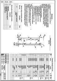
2 MODIFICATION OF THE ANTENNAThis section describes how to modify the antenna toconnect it to the antenna connector for transmission andreception located on the <strong>TKR</strong>-<strong>750</strong>/<strong>850</strong>/<strong>751</strong>/<strong>851</strong>.It allows to use as one antenna base by sharing anexternal antenna connector for both transmitting andreceiving.You must turn the power OFF before antennamodification.Follow the procedures below to modify the antenna.1. Remove the rear side top panel.Remove 6 screws (N33-3006-45, 3 mm diameter,black) and pull the panel up.2. Move location of C92 and C160 on the Final unit (B/2)for TK<strong>750</strong>/<strong>751</strong>.CN184-2. Remove 2 screws (N33-2606-46, 2.6 mmdiameter, gold) on the BNC connector fixed to therear panel and pull the ANTENNA CABLEbackward.Move location of C81 and C160 on the Final unit (B/2)for TK<strong>850</strong>/<strong>851</strong>.5. Cut the coaxial cable of the ANTENNA CABLE at theBNC connector side and remove the insulated part toperform soldering on the board.3. Remove the front side top panel.Remove 6 screws (N33-3006-45, 3 mm diameter,black) and pull the panel up.6. Connect the ANTENNA CABLE to the board.6-1. Solder the cut surface of the coaxial cablecenter pin to “RX” and the shield of cable to “E”.4. Remove the antenna cable.4-1. Remove the receive cable from the CN18 ofthe TX-RX unit (A/2).5 Modification Information (MOD) Version: 1.02 USA
6-2. Connect the pin connector side of cable to theCN18 of the TX-RX unit (A/2).2 MODIFICATION OF THE ANTENNA7. Short the “ANT SW” pads located next CN3 by solder.8. Reassemble the top panels after modifying theantenna cable.Note:" You must configure the operation mode of the channel asSimplex. Refer to the “Field Programming Reference” fordetails." To install the base radio on the location where the strong radiointerference may exist such as mountain top remote basesystem, we recommend you coupling the external antennaswitching relay. You can prevent the degradation of thereception performance caused by the internal antenna switchdiode.Order Number: KSG-90/00-50 TX/RX Relay kitAsk KENWOOD System for detailed information about thisproduct.Version: 1.02 USA Modification Information (MOD) 6
3 INSTALLING THE VOICE SCRAMBLER BOARDIt can install an optional Voice Scrambler board into the<strong>TKR</strong>-<strong>750</strong>/<strong>850</strong>/<strong>751</strong>/<strong>851</strong>. This section describes how toinstall the TRANSCRYPT SC20-460 in it. You can use theKENWOOD service part (E37-0808-05) when installingthe SC20-460 board.R4R3R2 R1! Requirement Items・ <strong>TKR</strong>-<strong>750</strong>/<strong>850</strong>/<strong>751</strong>/<strong>851</strong>・ SC20-460・ KENWOOD Part (E37-0808-05)・ Cushion TapeYou must turn the power OFF beforeinstalling the Voice Scrambler board.Note:" The required modification must be performed to avoidproblems, such as too small audio signals from the speaker,or too loud synchronizing noise." Refer to the Voice Scrambler board's instruction manual fordetails.4. Disconnect the cable connected to the SC20-460board.3.1 Configuring and Modifyingthe SC20-460 Board1. Modify the SC20-460 board and change the RX AudioInput method.<strong>TKR</strong>-<strong>750</strong>/<strong>850</strong>/<strong>751</strong>/<strong>851</strong> output a received audio afterDe-emphasizing to input into the option board.Therefore, it might be necessary to modify the voicescrambler board.(Confirm your SC20-460 is enabled de-emphasis.)1-1. Cut the foil between E52 and E53.1-2. Solder the position between E51 and E52 toconnect them.1-3. Solder the position between E53 and E54.5. Solder the KENWOOD service parts (E37-0808-05)cables to the SC20-460 board. You must connect thepart as shown in the as shown below. (Refer to 1.4 14-pin Connector (CN601).)BeforeE51E52E53E54AfterE51E52E53E543. Change the constant in conjunction with the TX/RXAudio level.3-1. Replace R1 with 100 kΩ and R3 with 100 kΩ inconjunction with the RX Audio level.3-2. Replace the R2 with 6.8 kΩ and R4 with 6.8 kΩ inconjunction with the TX Audio level.Before modificationAfter modificationR1, R3: 100 kΩ R1, R3: 100 kΩ (No modification)R2, R4: 100 kΩ R2, R4: 6.8 kΩ7 Modification Information (MOD) Version: 1.02 USA
3 INSTALLING THE VOICE SCRAMBLER BOARDSC-20-460 E37-0808-05 CN601No.ASignalnameBIN.CODE8Color(WHT/YEL)No.SignalnameColor1 TXO YEL24 mm 24 mmBBIN.CODE4(WHT/GRN)2 TXI ORN33 mm 33 mmCBIN.CODE2(WHT/RED)3 RXO BLUDBIN.CODE1(WHT/BRN)4 AC VIOE IRQ N.C. 5 BC11 BUSY N.C. 6 BC223ECHOPTTINDICATORN.C. 7 BC3N.C. 8 BC4WHT/BRNWHT/REDWHT/GRNWHT/YELNote:" The 3M cushion tape having a double-sided adhesive tape hasfollowing thickness.No. 4016 (or No. 4416): 1.6 mm (1/16 inch)No. 4008 (or No. 4408): 3.2 mm (1/8 inch)" The above sizes are reference values. You must cut thecushion tape into the same size as the Voice Scrambler.7. Stick the cushion tapes both side of the SC20-460.4 EMG N.C. 9 PTI BRN5 TX IN (YEL) 10 CLRC WHT6 RX IN (BLU) 11 RXI GRN7SCRAMBLE(WHT) 12 PTO GRY8 PTT (GRY) 13 8C RED9 GND (BLK) 14 GND BLK10 + V (RED)11 RX OUT (GRN)12 TX OUT (ORN)Note:Figure 3-1 Connecting the SC-20-460The KENWOOD service parts (E37-0808-05) have aconnector allowing you connect it to CN-601 of the <strong>TKR</strong>-<strong>750</strong>/<strong>850</strong>/<strong>751</strong>/<strong>851</strong>.6. Prepare the cushion having a double-sided adhesivetape. In this case, the cushion tape (No. 4008,No. 4016) manufactured by 3M can be used.Cut the cushion tape in the same size as the SC20-460 (24 mm x 33 mm).Version: 1.02 USA Modification Information (MOD) 8
3 INSTALLING THE VOICE SCRAMBLER BOARD3.2 Installing the SC20-4603-2. Remove two connectors (CN600, CN613).Follow the procedures below to install the board into the<strong>TKR</strong>-<strong>750</strong>/<strong>850</strong>/<strong>751</strong>/<strong>851</strong>.1. Remove the front side top panel of the <strong>TKR</strong>-<strong>750</strong>/<strong>850</strong>/<strong>751</strong>/<strong>851</strong>.Remove 6 screws (N33-3006-45, 3 mm diameter,black) and pull it up.2. Remove the FRONT PANEL of the <strong>TKR</strong>-<strong>750</strong>/<strong>850</strong>/<strong>751</strong>/<strong>851</strong>.Remove 6 screws (N33-4008-45, 4 mm diameter,black) and pull the FRONT PANEL forward.CN600CN6133. Remove the FRONT PANEL of the main unit.3-1. Unhook 4 hooks located on the top and bottom ofthe FRONT PANEL and pull it forward.You must be careful when removing the FRONT PANELsince the panel is connected to the main unit board with thecable.4. Remove R742 and R653.R653R7425. Install the SC20-460 board.5-1. Connect the connector on the SC20-460 board tothe connector (CN601) on the PCB (TX-RX unit B/2).9 Modification Information (MOD) Version: 1.02 USA
3 INSTALLING THE VOICE SCRAMBLER BOARD3.3 Configuration with theSoftwareTX-RX unit (B/2)CN601You can write the Voice Scrambler information to therepeater using the KPG-91D after installing the board.Follow the procedures below to write the Voice Scramblerdata to the repeater.1. Install the KPG-91D in the PC and start the program.The Main window of the KPG-91D appears.5-2. Peel off the cover of the tape on the rear surfaceof the SC20-460 board and install the board to thefollowing location.Mount and fix the SC20-460 here.Figure 3-2 KPG-91D Main window6. Reassemble the repeater after installing the SC20-460 board.Note:In case of test the operation of the <strong>TKR</strong> in PC Test Modeand adjust the maximum deviation after installing the VoiceScrambler board, the audio signal emitted from the localmicrophone is not modulated. In this case, you must removethe 12-pin cable connected to the CN601 connector of theTX-RX unit (B/2) and perform soldering on the land of theDisplay Unit. (Refer to the figure below.)Note:Refer to the “Field Programming Reference” for how toconnect the <strong>TKR</strong>-<strong>750</strong>/<strong>850</strong>/<strong>751</strong>/<strong>851</strong> to the PC and install andstart the KPG-91D.2. Select “Program” > “Read Data from Repeater”. Clickthe icon on the Toolbar.The “Read Data from Repeater” window appears.3. Click “Read”.You can read the configuration data from the <strong>TKR</strong>-<strong>750</strong>/<strong>850</strong>/<strong>751</strong>/<strong>851</strong> with the KPG-46 programming cableby using the KPG-91D.4. Select “Model” > “Model Information”.The “Model Information” window appears.5. Select “Voice Scrambler” from the “Option Board”dropdown list and click “OK”.12-pin cableSolder here toconnect the12-pin cable.Figure 3-3 Model InformationVersion: 1.02 USA Modification Information (MOD) 10
3 INSTALLING THE VOICE SCRAMBLER BOARD6. Configure the “Scrambler Setting” to be enable andselect scrambler code for each channel.7. Click “Write”.You can write the configuration data containing theVoice Scrambler information to the <strong>TKR</strong>-<strong>750</strong>/<strong>850</strong>/<strong>751</strong>/<strong>851</strong>.Figure 3-4 Channel InformationRefer to the “FPRG 6.2.17 Voice Scrambler” fordetails.7. Assign the “Scrambler On/Off” function to a functionkey in the “Key Assignment” menu, if needed.Figure 3-5 Key AssignmentRefer to the “FPRG 6.5 Key Assignment window” forhow to configure the function.8. Or assign function port to scrambler on, off or on/off.Figure 3-6 Function Port9. Select “Program” > “Write Data to Repeater” or clickthe icon on the Toolbar.The “Write Data to Repeater” window appears.11 Modification Information (MOD) Version: 1.02 USA
4 MODIFYING THE DC POWERIt is possible to modify the DC power to prevent the <strong>TKR</strong>-<strong>750</strong>/858/<strong>751</strong>/<strong>851</strong> is turned ON with the erroneousoperation of the power switch. With this modification, theDC power is always turned ON regardless of the powerswitch operation.Follow the procedures below to modify the DC power.It must turn the power OFF before DC power modification.1. Remove the front side top panel.Remove 6 screws (N33-3006-45, 3 mm diameter,black) and pull the TX-RX PANEL up.2. Solder the PSW part located on the left side of the TX-RX unit (A/2) to make a soldering bridge.TX-RX unit (A/2)Solder here to bridge.3. Reassemble the repeater after modifying the DCpower.Version: 1.02 USA Modification Information (MOD) 12
5 EXTRACTING RSSI SIGNAL FROM THE ACC 25-PIN D-SUB CONNECTORIt is possible to extract the RSSI signal from the pin 1 ofthe ACC 25-pin D-Sub connector (Default: NoConnection).Follow the procedures below to modify the connector.Note:The part number of the ACC 25-pin D-Sub connector is“E37-0904-05”.It must turn the power OFF before modifying the connector.1. Remove the FRONT PANEL of the <strong>TKR</strong>-<strong>750</strong>/<strong>850</strong>/<strong>751</strong>/<strong>851</strong>.Follow the steps 1 - 3 in “ 3.2 Installing the SC20-460“.2. Cut the connector 27-pin cable (CN606) located onthe printed board of the “E37-0904-05”.Note: Cut and remove the wire from the top of connector.3. Solder the wire to the RSSI land of the printed circuitboard.Connect the wire here.4. Reassemble the repeater after modifying theconnector.13 Modification Information (MOD) Version: 1.02 USA